So I’m planning to build some projects by Syntonie.fr like the ‘AVE MOD’ and the ‘VISUALIST’.
Now I found the circuit diagrams on their GITHUB .
I have a basic understanding of electronics but some things I just can’t figure out.
This is the downloadlink to the circuit diagram of the AVE MOD.
First, how does it work when there’s multiple power sources in 1 circuit? 1 of the circuits connects 7 times to a 12V power source and 4 times to a 6V power source. Are those just 2 batteries of 6V and 12V? And how do you know where the ground connects to? (cause there’s 12 grounds noted)
Second, there’s 3 different circuits, but I don’t understand how they connect to eachother?
Thanks in advance and sorry if my questions are really obvious
Greets, Lucas
i think AVEMOD would be a great place to start building some video circuits. from what i understand the VISUALIST is more complex and needs some harder to find parts, so i would recommend getting familiar with some smaller/easier projects before trying that one.
im guessing you are intending to build these on a strip/breadboard from the schematics ?
another (easier) option is to grab a pcb (then all the traces are already connected , you only need to think about placing components )
but if you want to build from the schematics, then yes multiple ground / power source symbols is just a short hand way of saying all these things are connected together
so in this schematic every part where it says GND should be connected, and same with every part it says +12V
so with this in mind you can see that even parts of the schematic that look disconnected actually are connected through these label shorthands.
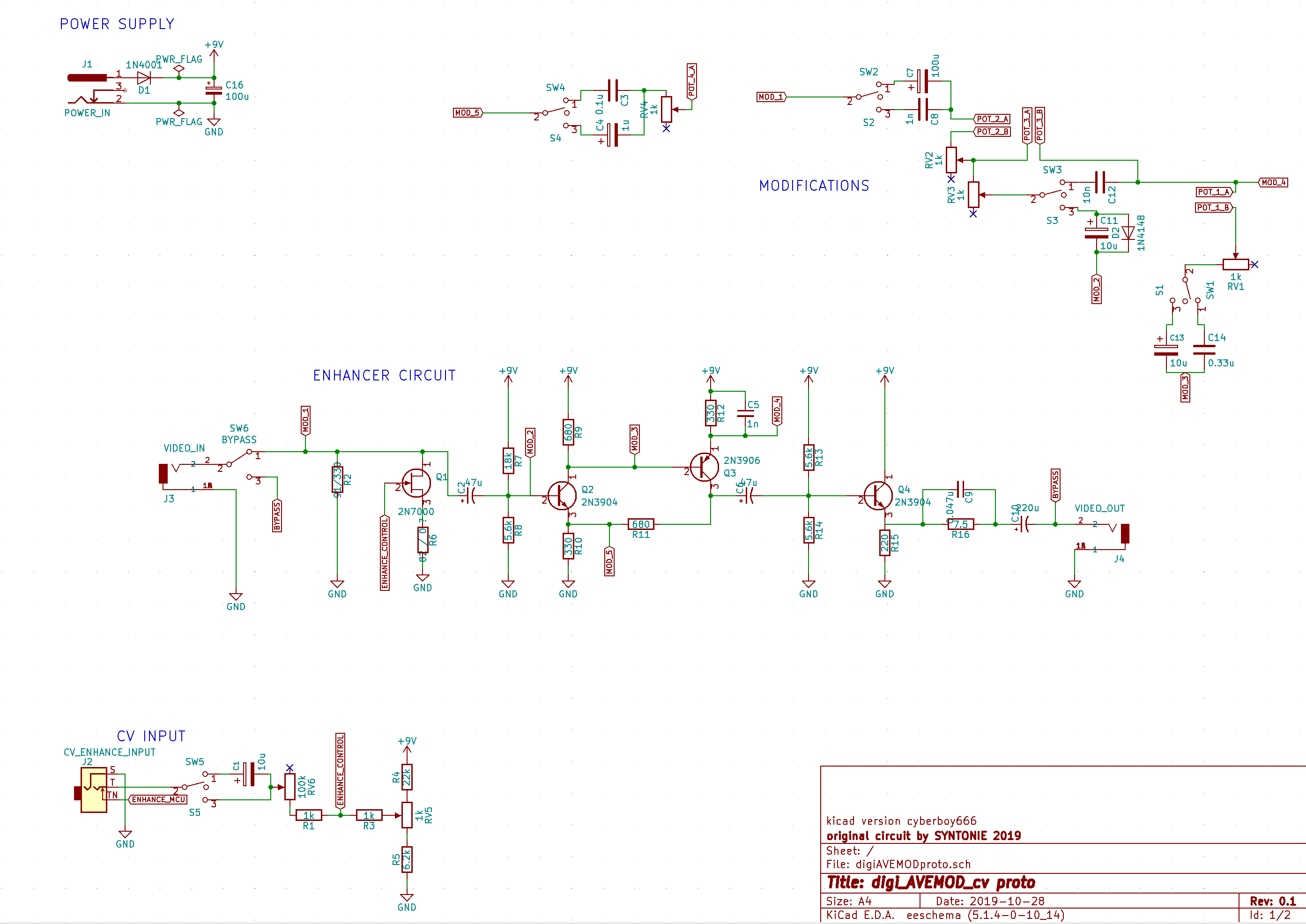
some schematics use labels for other parts of the circuit too in an effort to make them easier to read. heres a version of the avemod circuit i was working as an example (debatable if its actually easier to read ):
I’ll get all the materials at once since I prefer not to order to much different packages from across the globe I’ll try to find as much as I can on tayda.
The circuit boards are not available at the moment in his webshop + I’d like to learn how to build circuits from scratch, so yes, I’ll give it a try on a stripboard!
later on, I’d also like to learn how to make my own PCB’s.
But so, there’s 2 different power sources, right? 6V and 12V? And then, the GND’s are all connected together, so it doesn’t matter if they lead to the -side of 6 or the 12V battery?
As for the labels, I can’t seem to find them, could you maybe point them out to me?
Thank you so much.
Also @BastienL thanks for all the cool projects that you make so much more accessible for noobs like me!
About AVE MOD, I got a new version coming (mainly layout changes and proper CV input), so that’s why the board isn’t available anymore, however I’ve uploaded the gerbers for v2.3 so anyone can print boards for it.
Hope to have the new ones available shortly.
Else stripboard is fine, the circuit is quite simple, I’ve made the first versions of AVE MOD, Discret11 and TRQ on veroboards before moving on making my own pcb
For the voltages, you’ll connect all the point labelled 12V together, and then to your power supply (can also work with a 9V battery, the resistors value could be changed but it works pretty fine with 9V). Then the 6V is done with a voltage divider (R12’ and R13’), so it will be divided the 12V from the power supply by a factor of two (hence 6V), in the case of 9V power supply, it will be 4.5V. This is to create a virtual ground for the op-amps, that way, I could adapt the audio circuit that was originally powered by a bipolar power supply (+12V/-12V) to a single 12V supply. It’s a bit quirky though, so sometimes it requires to adjust R1’ value to get a better modulation range, that’s why I replaced it by a simpler solution (can be seen on @cyberboy666 schematic, JFET as a voltage divider)
To resume, you don’t need two separates power supply, but one 12V or 9V supply, and the 6V/4.5V will be divided from it, then just make sure that it connects to all the other voltage labels on the schematic.
The audio part can be omitted if you don’t need it though, as for D3/R14 which is a power indicator.
About the Visualist, I’ve reproduced the board from the documentation, however I haven’t tested it and didn’t had feedback for it yet. Can be built on vero/stripboard also, there’s a lot of connections to do but surely doable with a bit of patience and care
The 2 obsolete parts are the trimmer coil and MC1377P. The trimmer coils are a bit hard to find, there is some on eBay but there is different pinouts it seems, it can also be omitted/bypassed, it’s role is to filter out the colors from the composite video signal, but it will work even with color, however it looks a bit better with a black and white video signal at first.
MC1377P are not available through electronic suppliers, however you can find some on eBay or UTSource, can also send you a few depending on where you’re located.
Appart from those, you should be able to source most of the components required for both ave mod and visualist from Tayda.
Thank you for the quick replies! That made it a lot clearer!
I’ll try to figure it out from here on
Also very excited to see what the next version will look like.
I’ll let you know when I finished the project!
I think I found a place in UK that still supplies the MC1377P, I’ll have a look where I saved that. If not, I’m located in Belgium so shouldn’t be too far?
Have a good day!
I’ve been trying to figure out how to get the AVEMOD/CBV001S on stripboard, but I’m finding it tough to consolidate and lay it out. Do you by chance have any pictures of those prototype stripboard versions that you could post? It would mean a lot to me
I don’t have any good pictures of those unfortunately, and since it was made on veroboards and not stripboards, it’s quite a mess of wires, so won’t be super helpful I guess.
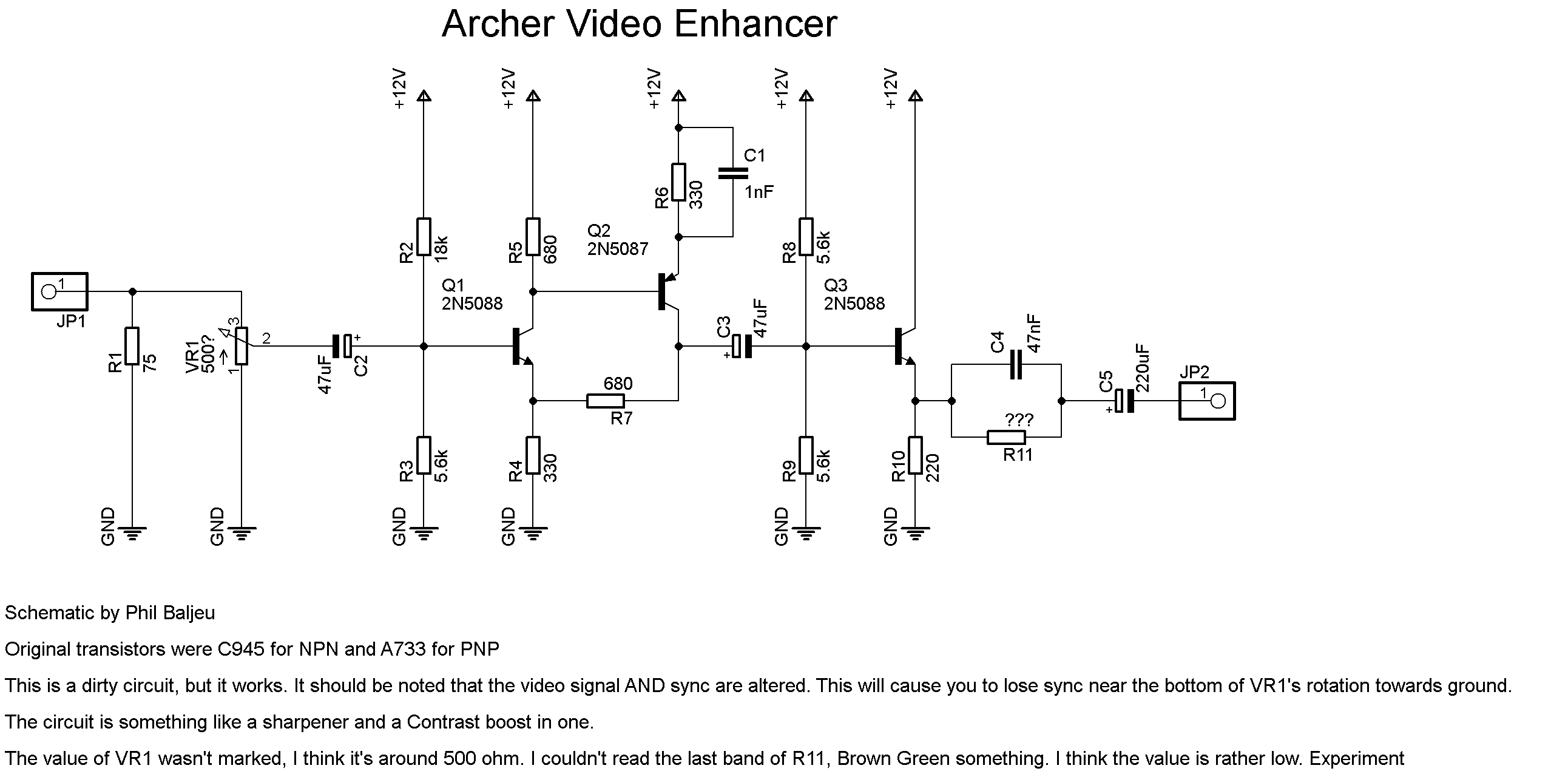
I’d recommend using a software such as Fritzing to plan your strip board. Also, it’s probably easier to start by building the core enhancer circuit https://syntonie.fr/wp-content/uploads/2017/11/ave_595.png and then add the bends/external modulation. Let us know how it goes
 and good luck with your circuit adventures !
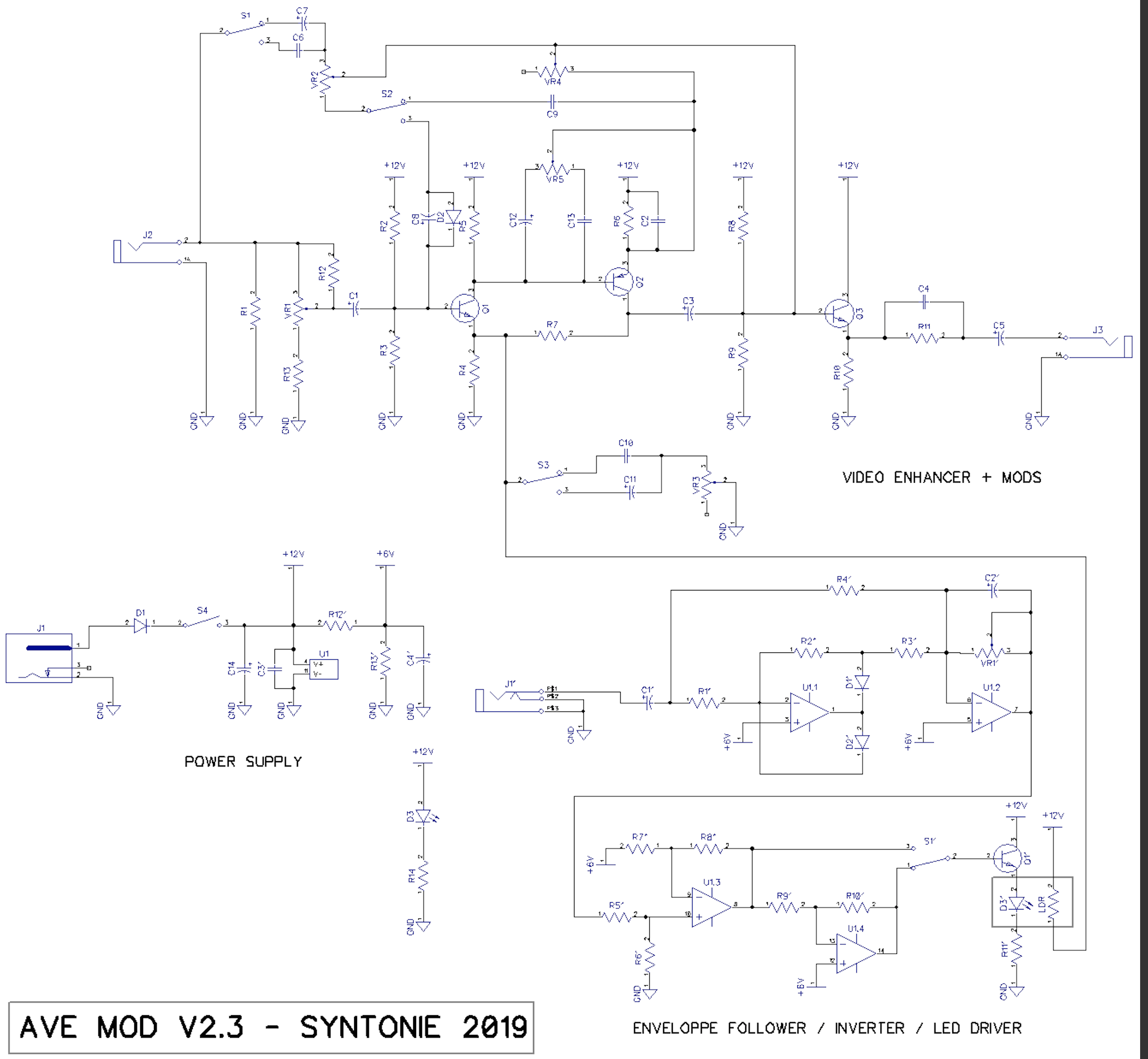
 ):
):

 I’ll try to find as much as I can on tayda.