next tuesday i am giving a talk as part of fu:bar festival. the talk is about:
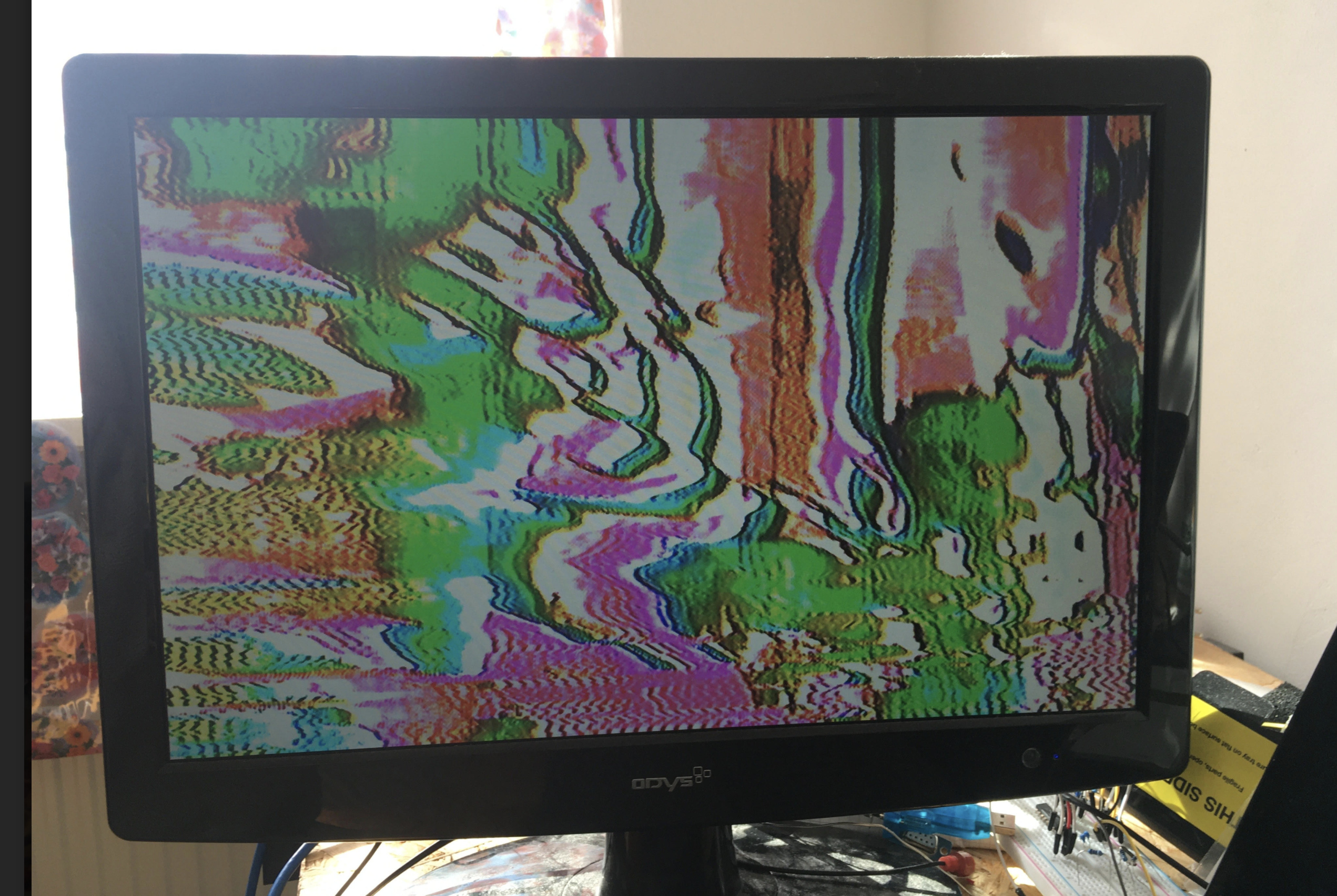
what real-time / analog glitch-art is and how it can. be made
understanding some technical challenges with displaying / capturing this kind of glitch art, and some common solutions
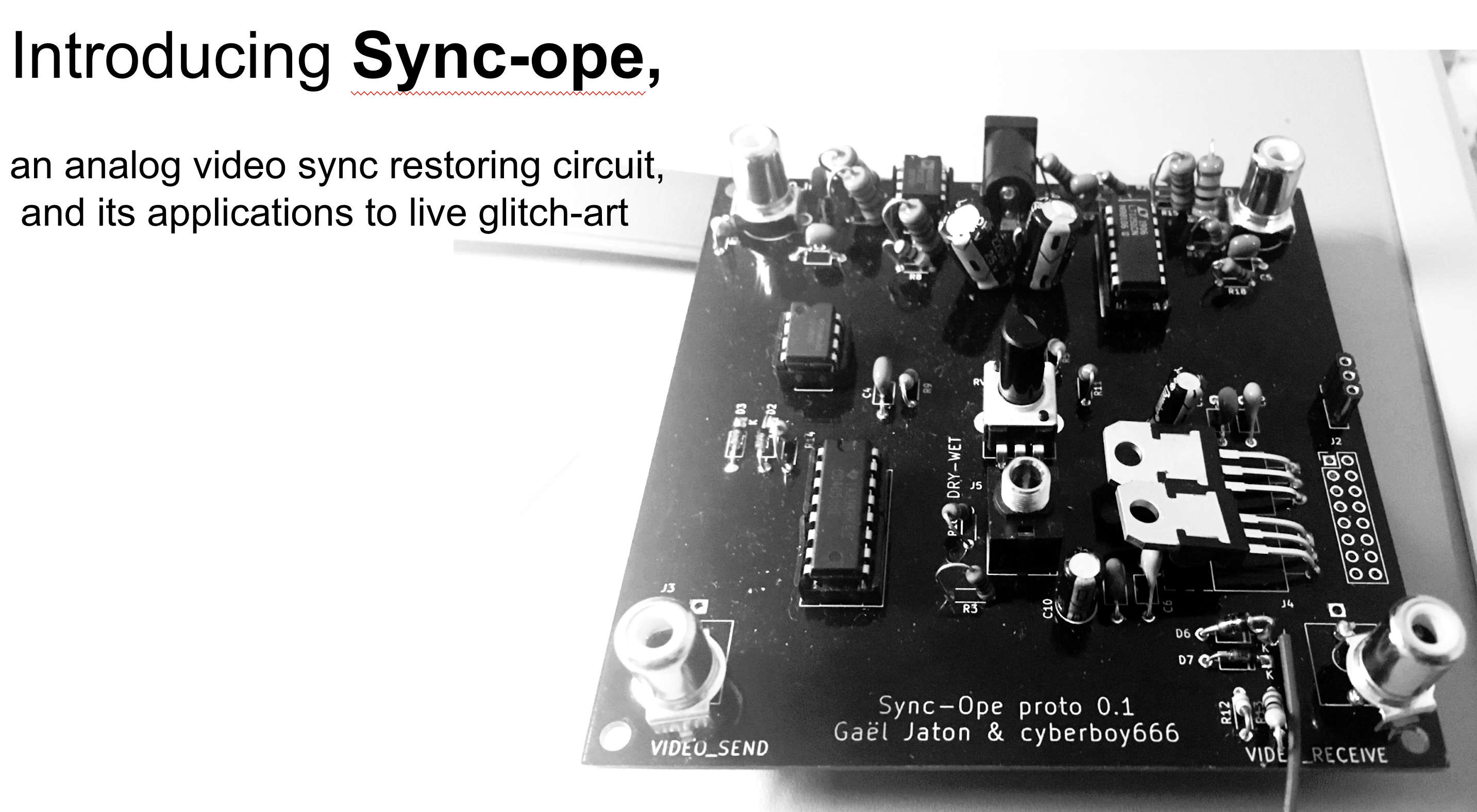
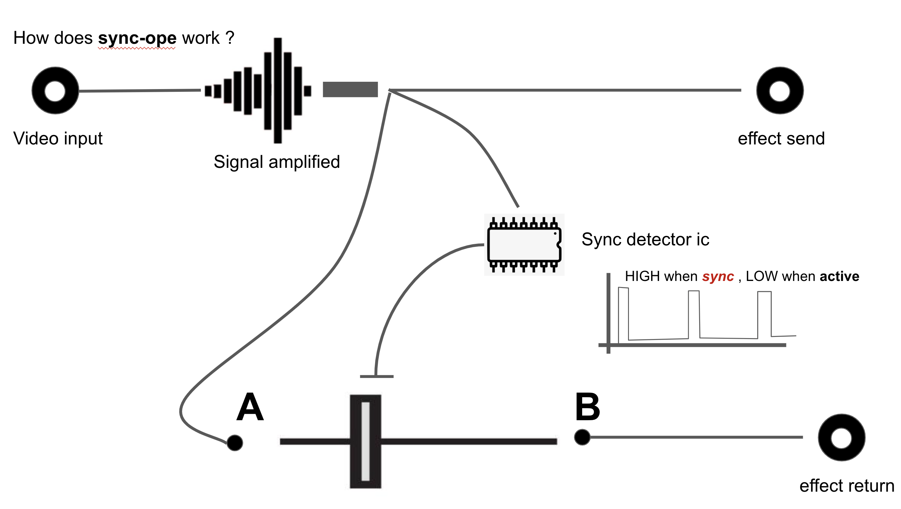
introducing sync-ope, a utility circuit Gael Jaton and i have been building and how it works
when: 18:00 CEST, tuesday, october 6, 2020
2020-10-06T16:00:00Z → 2020-10-06T17:00:00Z
i will post some more about this project on scanlines at some point, but if you wanna find out more/ see a live demo/ ask me some tricky questions i hope to see u therr !
thnx! yes looking forward to the performances/talks u are part of for vectorhack/fubar too. and yah i tried to do that but couldnt get the timezone part correct. updated now
some people use the video signal as an audio source. if you remove the sync signal, it will sound better . what @palomakop said about a syncless output , using the inverted crossfader cv signal might be an interesting feature.
there could even be an amplifier so that there could be a line out.
the crossfader is controlled with a squarewave / pulsewave . so the switching is pretty fast. with glitch in mind, maybe it is interesting to experiment with a slew / lowpass filter to see if you can stretch the point to where the sync stays good. that might help getting more ‘halfstable’ glitch effects.
note: if you need footprints for the composite ins, check on snapEDA.com if there is already one available. saves you from making one yourself.
if you make it modular, a switch pulse output might be useful
ps: these are just ideas . I don’t mean you have to implement them, but maybe ‘someone’ could experiment. (maybe I will. who knows?)
thanks for the feedback ! these all sound like good ideas.
ahh i understand now why one might want to remove sync from video signal. i can imagine a small circuit with just lm1881 and cd4069 to strip sync too. also it could be added into this sync restore circuit but this kind of feels like a slightly different utility to me
iwas confused about the composite footprint comment until i looked at my picture again lol -> yes i have footprints for this, just hadnt decided what kind of jacks to put on the board yet haha. current version has both 3.5mm and rca. although still undecided what to include on a euro version where space is more valuable …
open to exploring / collaborating with you on this if you are interested. can send u a pcb when we get a euro-proto fabd
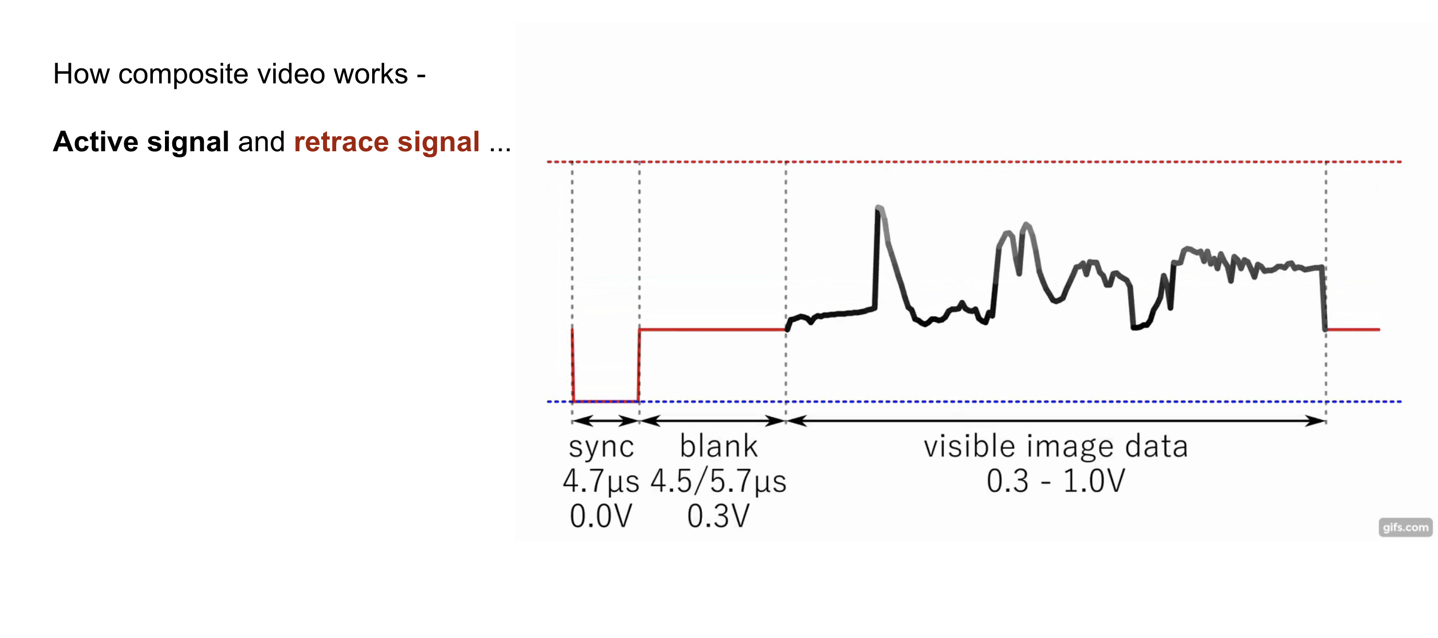
I was thinking that maybe the sync signal could be clipped before the send output, since it is DC restored, it just mean clipping everything under 0V, but this probably needs to be optional if the user wants to use it with video gear, as some will require to have the sync to operate.
Having two separate send/return IO, one for composite video, one for other signals can be great, as composite doesn’t need the sync stripping and requires 75 ohm termination/2x gain.
That’s what I had in mind to keep a euro module under 4HP, having a dual footprint for RCA/jack, so it can be built for one use or the other. The module could be made bigger to allow for both though.
Cause both use are super relevant: it’s a good way to stabilize glitched video, but also opens endless possibilities to process the video signal with audio gear or even video rate modules.
Also depends on how simple you want to keep it as the current board works quite well already, only tested with composite so far though.
nice Project!
i am really interested to build one.
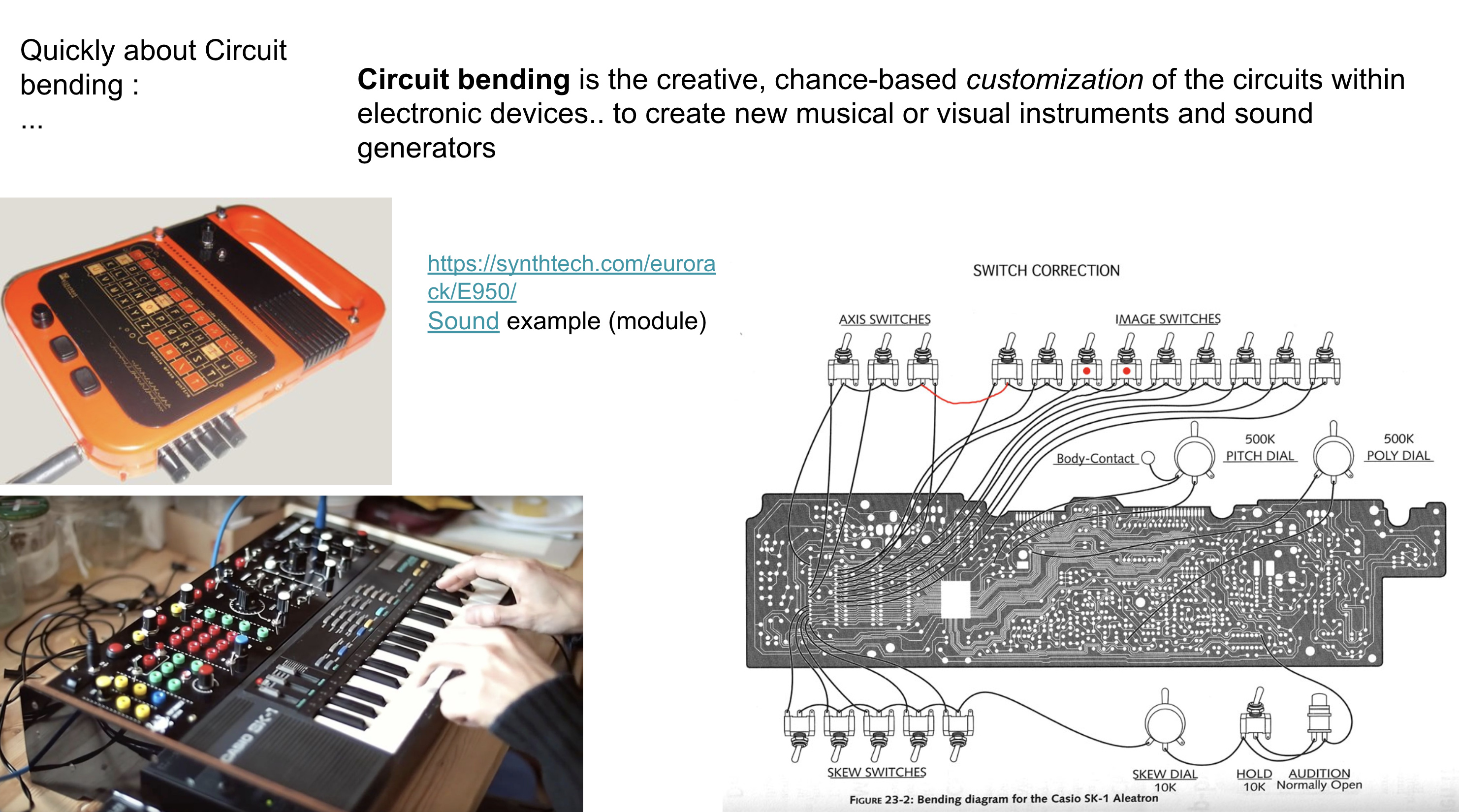
i had the idea to mod a ‘inverter’ effect i own into something link this - but never got round to actually do it .(it works in a similar way first splitting the sync stuff from the signal, then inverting the video and put sync back on)
am i missing the link or is the full documentation not open yet?
i’d be interested in a PCBs or participate in a group order
all the files are here GitHub - cyberboy666/sync_ope: effect send + sync restoring circuit - adapted from a gael jaton design , already you can order some pcbs from these gerbers, or pm ur address i will sell some pcbs from this current batch i have. still the project is always evolving, and with feedback and ideas from others some changes may be made to make it better yet. (plus more documentation etc to come)
ps your inverter circuit sounds similar to this luma_croma_inverter circuit here, from @schaferob’s design
Hi everyone,
there was an issue on schematic, gain on first buffer amp was wrong, github project page is update (but PCB not yet).
If you get a V0.1 or v0.2 pcb board, here is a picture of the fix mod :
you have to bypass C1 and move R2.
Then an additional IC is coming for delay burst signal from lm1881 (3µs), (actual circuit crush the burst signal, resulting poor color rendering).
The last thing we didn’t implement is DC restoring, I didn’t have any problem with my various devices, but do you thing it could be critical?