Open source FPGA based video synthesis platform

Howdy! i’ve been talking with some folks about this for a bit, and then eric schlappi and i just had a conversation today about working together on getting an open source FPGA environment set up for doing video i/o. We thought it might be kind of handy to have a discussion board side of things in addition to a github and also would like to know if anyone else is interested in participating, @BastienL maybe?

main things to think about for getting started would be deciding on some basic hardware sets for experimenting with.
fpga open source dev boards

ulx3s

orangcrab

more info to come when i get a second, i will be heavily documenting my part of this project b/c thats usually how i learn things. but mainly interested atm if anyone else would enjoy jumping into this zone along with us! basically a video synthesis system based off of this would be able to have a similar form factor to all the pi based stuff but with the added bonus of higher quality analog and digital i/o and more flexibility in terms of hardware add ons!

9 Likes

Going to get in the thread and drop some links to the open source toolchain:
yosys
nextpnr
Project Trellis

For those that aren’t aware the proprietary fpga tools are quite difficult to use and the advent of the open source toolchain has been a big deal. Since creating the open source toolchain involves reverse engineering the bitstream there are only two FPGA families really supported so far, the Lattice ICE40 and Lattice ECP5. There is also a lot of work being done on the Xilinx Artix 7 series but it isn’t really ready to be used yet (I think).

The two boards above both have an ECP5 on it and enough resources for video. The Orange Crab is very minimal but has DDR3 ram, whereas the UL3Xs has lots of extras. We would probably want to instantiate a riscv processor (the picrorv32 is an example) for state machine and UI control then do the heavy lifting in pure logic (verilog).

I’ve spent the last year and change working in this toolchain for a eurorack module (and am currently laying out a board with an ECP5 on it) but once my schedule clears a little would be happy to contribute towards the hardware design of an open board for video processing.

4 Likes

@andrei_jay and @special_chirp that’s an awesome idea! I’ve really limited knowledge with FPGA as I only recently started messing with them, got a Xilinx Coolrunner CPLD a few months ago do to a simple composite sync generator, so I’ve been using a CMOS CMOD2 board with a JTAG programmer and Xilinx IDE, which isn’t the most convenient. Really interested to see more about open source hardware/software side of things when it comes to FPGA. @cyberboy666 told me about this IDE, didn’t tried it yet

apio

That’s fun cause I was thinking of a digital video oscillator/shape generator, and Eric’s Three Body module immediately came to my mind and was about to ask him a bit more about it, so super happy to have you here :slight_smile:

3 Likes

Hey @BastienL!! Thanks!

That’s awesome you are experimenting with fpgas!
Another board to look at (which I did the first half of the Three Body prototyping with) is the icebreaker. On that page there are links to examples of video done with it and a hdmi output PMOD. The ice40up5k it uses can be pushed to do 720p, but that is with very optimized logic. It’s a good chip for glue logic and getting started though.
Apio is pretty cool but a bit resource intensive. I was using it for a bit then switched over to just using a text editor for writing verilog (currently using Sublime Text) and building my bitstreams with a makefile (in linux).

There’s no reason the Three Body can’t be pushed into video rate, just gotta move to more expensive ADC/DACs :slight_smile: Happy to answer any questions you have. Also stoked to see what you are working on!

3 Likes

hii and whoo - this all sounds great !

i also have been eagerly following the development of fpga open-source toolchain / development. sounds like a sweet project , would love to help if i can…

both the orangecrab and ULX3X look good. i actually picked up a tinyFPGA bx to start learning a little about all this, although havnt even got around to plugging it in yet. it has a ICE40LP8K , and usb programmer on board. smaller than the ECP5 option (i have no idea how many luts/cells you need for video stuff??) , but for under $40 figured it was a good place to start before sinking +$100 on something i might not use…

so yeah, im keen - but know nothing about verilog rn. (also thinking i might need to tap out of hacking soon to finally try learn german for a bit - after living here for over a year lol :sweat_smile: , but lets see )

oh - i see @special_chirp says above that ICE40UP5K can only just do video , so yeah maybe my tinyFPGA is alil small too , but lets see , somewhere easy to start for sure

UPDATE; also just seen that tinyFPGA has a board coming soon EX based on the ECP5 , dont know enough yet to really say whats the better choice just puttin it out here :slight_smile:

4 Likes

awesome! The tinyFPGA BX is also nice, I actually have that one as well. In some ways the ICE40LP8K is a little more powerful than the ICE40UP5k (more LUTS, faster fabric) but it doesn’t have any DSP blocks. One tricky thing about doing things in logic is multiplication. Yosys will synthesize addition and subtraction for you with minimal logic count, but multiplication is -very- expensive in terms of fabric. The DSP blocks contain hardware multipliers, which are pretty fast usually, but you have a limited number of them so you generally need to pipeline and time multiplex them.
The TinyFPGA EX is will be another good choice, I don’t think there is a timeline on when it’s actually coming though?

The limitations of the ICE40 aren’t so much in terms of logic elements, it’s the fabric speed and small number of multipliers. You -can- get a 75MHz pixel clock out of it (the speed I’ve seen for 720p), but generally once you have a lot a paths (your longest logic path between clock cycles dictates your max clock speed) I’ve found something like 30MHz to be more of a practical limit.

I’ve seen a figure of 145MHz pixel clock tossed about for 1080p60 (though that might have been only 4 bits per color). I -think- this achievable with the ECP5 with some headroom left over. There are also different speed grades of ECP5 as well as different sizes (number of LUTS and multipliers).

I think a near future goal is to determine the specs we are looking for (resolution, number of channels, target pixel clock, input and output formats, amount and speed of RAM).

@andrei_jay and I were talking about maybe trying to do the composite to component decoding in the analog realm then capture the three channels seperately? @BastienL have you been looking into these things?

4 Likes

If you want someone to design hardware let me know. I am building a scriptable video platform instrument with a compute module. I would love to work with you , with potentially some of you talented software designers.
( i am also nearly done an open source controller for this/other projects).

4 Likes

@andrei_jay and I were talking about maybe trying to do the composite to component decoding in the analog realm then capture the three channels seperately? @BastienL have you been looking into these things?

I have been.It is somewhat complex , but its a part of the module/instrument i am building.

@special_chirp for now I was looking at off-the-shelf decoder ICs as ADV7280 or TVP5150, they aren’t particularly cheap but they do a lot of the heavy work.

To do composite to component:

  • first Y and C needs to be separated from the composite signal, I was looking into analog ways to do the filtering, I’ve only tried simple filters for now and I’m not able to completly kill chroma from luma, so most monitor/capture cards still picks up colors, quite dark, but still colors.
    Then there is more complex analog filters, like this Kramer Composite to YC, but it uses a 390ns obsolete delay line, trimmer coils and only work for PAL.

Then, I got another Kramer Composite to S-video that works with both PAL and NTSC, but it relies on a digital YC separator chip by Motorola (obsolete of course), and requires a subcarrier genlock (PLL+crystals), so not very practical either.

But maybe it’s less critical if you convert the YC to component afterwards, cause at first I was mainly looking to get a proper black and white signal. I was checking my Panasonic AVE5 input circuitry, and the filtering is done using an passive analog filter (like 3 stages encased in a metal case) and it seems that it left a bit of chroma in luma, but then it was sent to a specific IC that does the YC to component conversion.

Here’s an interesting article about this subject https://www.renesas.com/br/ja/www/doc/application-note/an9644.pdf

So a completely analog decoding is sure possible, but seems quite complex, even more if it requires to be PAL/NSTC compatible.

From what I understand, Analog Devices decoder samples the whole CVBS signal at the input (10-bits at 57MHz), and then does all the decoding digitally, allowing for precise comb filtering and such. So maybe that would be a good compromise, allowing to keep an hand on the all process after digitizing, compared to completely integrated decoders that are less flexible.

I’ve build a board with those ADV decoder/encoder, but couldn’t get it to work yet, I’m also learning about I2C communications at the same time so that doesn’t help :sweat_smile:

3 Likes

I2C would be fantastic for an application like this. I’d say potentially asking Lars from LZX how he did the composite and the NTSC/PAL on the Vidiot would be fantastic start on this project.

1 Like

I think the Vidiot only process black and white video, in a similar way as the Cadet Video Input does, you can send colors, but they will be re-encoded at the RGB encoder stage along with the generated subcarrier, so does a bit of rainbow effect as both subcarrier are mixed together (and of course, original video color information will be lost as the signal will probably be blanked), that’s why it’s usually recommended to use a black and white video signal to start with. I guess that beside the sync generator, the Vidiot is mostly analog.

Lars commented recently to someone asking about decoder chips on Video Circuits, and he mentionned the TVP5150, so that’s probably what is used in the Chromagnon, which takes composite/YC/SD Component/HD Component (and maybe more? :stuck_out_tongue:)

i2c not really accessible in the open source fpga workflow. It requires a lot of software overhead, you would have to instantiate a CPU then write a driver to handle it. It looks like analog devices has a lot of other analog to digital encoder options:

I would pick one of the ones with the “pixel bus” ie parallel outputs. ADV7181D looks pretty nice.

The TVP5150 may also be workable, not familiar with the output video standards it references.

The FPGA is sort of a brute force solution. Writing a driver for a two wire interface like i2c (that usually comes for free in microcontrollers) is actually really hard. However devoting 36 pins to a parallel bus from a 381 pin chip with 180 or so gpio pins is easy. Anything that can be done in parallel is better, serialization is hard (all opposite of microcontrollers).

It may also be possible just get tough and write a decoder core for verilog but that sounds like a pretty serious project on its own.

From what I’ve seen on those decoders datasheet, both AD and TI ones needs to be setup using I2C. I’ve been using an arduino for now, could probably be replaced by a small atmega as there is not much register to edit, also depends of what settings needs to be accessible. But true that if everything can be done by the FPGA without a micro that would be better.

Analog decoding would ask for some control to detect the standard, and then switch stuff accordingly to accommodate for the standard differences, could be done by sending extracted sync to the FPGA and control switches I guess, it would solve most of the logic required. So to sum up it requires the following circuit (might be incomplete):

  • Sync extraction (LM1881 or LMH1981)
  • Sync genlock (PLL+VCXO for exemple) to generate a synced clock for the FPGA
  • Subcarrier genlock to be used for the color demodulation stage and pixel clock
  • Composite to YC separation filters (we now have Y)
  • C to R-Y/B-Y color demodulator, looks like it can be done by multiplying C with sine and cosine of the genlocked subcarrier

chromademod
(this picture is for a digital implementation, from here)

NTSCDecode

  • Then deinterlacing to get progressive component, which can be done with the FPGA.

There’s is a few open source project for video capture as OSSC or hats for RPi, but most of them relies on an integrated decoder it seems. RPi hats can be quite simple as some ADV chips outputs MIPI CSI-2 which seems to be a digital camera standard, @andrei_jay and @cyberboy666 should have more insight on this.

I was interested by the ADV7280A cause it outputs an 4:2:2 8-bit YCbCr/digital component (ITU-R BT.656), that can easily be interfaced with an encoder like ADV7391 (that will convert the 8-bit back to analog composite/YC/YPbPr). ADV7181D samples at a higher bitrate, not sure what it outputs though, TVP5150 seems to output YCbCr too.

Then, about doing the decoding in digital, I don’t really know much about digital filters so seems rather complex, but looks like a good in-between analog decoding and decoders-on-a-chip.

2 Likes

Is there an advantage to having YCbCr inside the FPGA?

The FPGA verilog code I have played with so far all use an RGB color space, so it is super easy to manipulate each channel, then go out to DVI (like this PMOD). Would also be easy to use an triple DAC (like this adv7123 )then feed an encoder IC like the AD723.

I had initially thought about using the above for output and something like three of these AD9283 high speed ADCs for input.

The scheme for sync extraction and genlock shown above looks doable. A few multipliers and a few digital filters, -not- trivial but definitely doable.

I kind of like the idea of rolling our own instead of using an encoder to allow for non-standard video signals (@andrei_jay was bringing up the ability to tailor it to handle high frequency modulation and corrupted/circuit bent video feeds).

My experience with most chips that offer some sort of parallel bus output (or simple high speed serial interface like I2S or SPI) for FPGA interface is that they have the I2C interface for configuration but it is optional to use it. I’ve set up several different audio ADCs and DACs with the ICE40 and ECP5 this way so far.

There appears to be a an open source MIPI CSI-2 VHDL core. SO it may be possible to use that.

1 Like

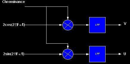
No you’re right, it’s better to have RGB inside the FGPA, as it will be easier to work with, however, I don’t know if it’s better to acquire Component with the FPGA and then do the colorspace conversion to RGB in digital, or do the math with op amp in the analog realm and then digitize the converted RGB. I’ve got a small module that I’ll release soon that does Component to RGB conversion in analog, I’ll publish the schematic online but it’s greatly inspired from Linear Tech AN57
YPbPr2RGB
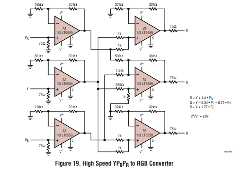
it just requires some precises resistor values to do the math, but nothing super elaborate, digital conversion might be more precise without the need of 6 hi-speed op amps + passives.
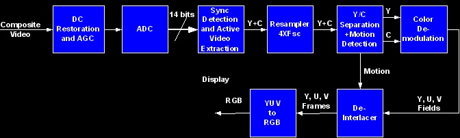
Component is useful in analog cause syncs are embedded in Y and it can be used for luminance based modulation, and it is easily converted to RGB as mentionned before, probably makes less sense in a digital system though, as the clock of the system will probably be derived from the composite signal sync with a PLL and VCXO (as it is done in Cadet Sync Generator), so we only need to sample the active part of the signal.

The only thing I’m not sure about on the analog path is the subcarrier genlock, as I wasn’t able to find a VCXO at subcarrier frequency, and it will probably require 2 of them (3.58MHz/4.43MHz), then it can also be done with a crystal oscillator as it is done here.

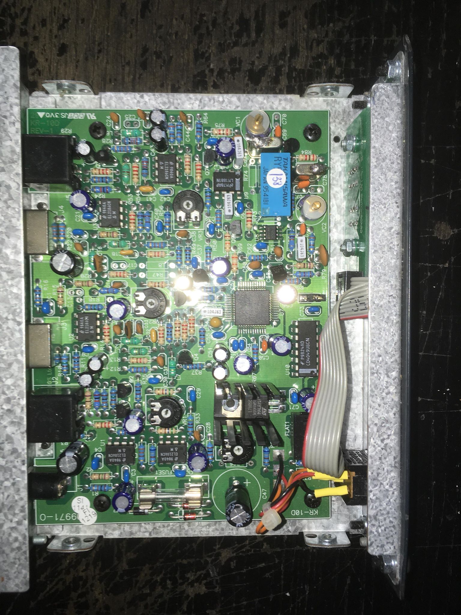
The full composite video signal is going into the 10nF that is tied to IC10c switch, controlled by the burst output of LM1881, so the switch only opens during burst, which let’s only the reference subcarrier through, then Q1 and associated components amplify the signal a lot to get a square signal. Then amplified bursts are phase compared to the signal generated by X1, and the output (PLL error signal) is used to compensate for this phase difference until both are in phase. Not sure how it will be adapted to NTSC, would probably require a different filter to amplify bursts and a different crystal, I think that’s what the Kramer digital YC separator I’ve posted earlier does: the front NTSC/PAL switch turns switches on and off to get the proper frequency depending on what is required, autodetection of the standard would be fancier :slight_smile:

About re-encoding back to analog afterwards, I was also thinking of doing DAC + RGB encoder, but figure out that it would be a little cheaper to get something like ADV7391, as it will take care of the digital to analog conversion and analog format conversion, only thing is that it can only output one format at a time (either composite, YC or component set through I2C) while going the DAC + analog RGB encoder would probably allow for simultaneous composite/YC/component out without requiring to be set up with I2C.

About non-standard/glitch signals, since the composite to component conversion (analog or digital) heavily rely on proper sync/color ref, I don’t really know how “flexible” it can be, cause from what I get, you need a proper signal at some point to derive all the clocks used by the analog and digital part, so I guess it requires to buffer the signal to be able to keep a portion that is in-spec, so everything continue to run despite the sync or burst being corrupted. It seems that a framebuffer is what’s makes the difference between capture cards that handles glitch well and the ones which does not, also depends of what the designer considered to be an in-spec/out-of-spec signal I suppose.

Anyway, I’ll see what other helpful schematic I can find about analog decoding, looks rather complex but surely doable.

In the case of the ADV chip I’ve tested, I2C isn’t really optional it seems: the chip is turned off by default and needs to be turned on through I2C, same for the clock oscillator (I replaced it at first cause I thought it wasn’t working as nothing was showing on the scope), as long as some “ADI special writes” that are registers that needs to be edited but are not really explained in the datasheet. The idea i had behind the board with the decoder/encoder chip was a converter first (to go from Composite/YC/Component to Composite/YC/Component and also PAL/NTSC conversion), so here it would require to be able to edit the parameters through I2C continuously (at least when a setting is edited).

4 Likes

^^ agree with this. will help focus the brainstorming. also some rough ideas around potential cost, part sizes / diy-ablity / interfacing… maybe even some potential applications would be nice.

i dont know much about this in practice, but in my head was always thinking of using fpga in a hybrid circuit (something with both a uC & fpga). i know you can build softcore processes or whatever on em , but when real uC’s are so cheap, seemed to make more sense. for example i picked up a lil dev board like this running a STM32F401 for under $5 , maybe smaller (cheaper) fpga like ICE40s would be suitable if we ofload some interfacing logic to the uC, and use the fpga only for specific video stuff. (also then you get the i2c / whatever control protocols as a bonus)

still though, maybe this video-core stuff needs the fabric speed / multipliers anyways ?

2 Likes

yes i think one of my goals for this is a more general purpose platform for hybrid digital/analog computation and research in general a framebuffer/array of framebuffers is pretty crucial i think for much of what id be interested in exploring as well, not just for video delay/feedback but also for use as potential multichannel framesynchronizer/upscaler/proc amp. another neat thing to think about if we want to work with the component side of things is potentially being able to get down with HD analog signals so we can work with @schaferob s amazing stuff as well as try our own experiments with this mostly unexplored signal. and benefits to YcBcR is that it can be potentially simpler to also capture HDMI signals in that format as well as its not terribly difficult to go from that to RGB or HSV

1 Like

rad!! yeah I was kind of thinking of something between a dev board and a system on module (SOM) with: FPGA, a microcontroller (for i2c config), RAM, video in and out, USB for firmware/gateware updates, and a ton of header pins on it. That would allow anyone to add another PCB with whatever user IO and connectors they desire then sell it or remix it into whatever application they want.

does someone want to start a google doc or git for potential specs?

@BastienL you are totally right about needing the i2c for config.
@cyberboy666 in quantities of 100 or so the ECP5 LFE5U12 is only about $7.50 a piece, with the ice40 at about $6.50. The downsides are that it only comes in BGA packages and requires more power (still a low power device). I think for HD the faster fabric will be necessary and you will definitely need those multipliers for any filtering application.

1 Like

i’m just put orders in for one each of the ulx3s and oragncrab, I wanted to double check with @special_chirp that for a riscv processor is there any need to get an external processor for that? apologize for n00b questions, i’m having a real dickens of a time trying to find sources of info for this kind of stuff thats dumbed down enough for me to get at without hours of google mining

Theoretically you shouldn’t need an external processor. I can’t confirm in practice until I get a softcore running on my orange crab, which is on my desk but I haven’t had time to explore.

The best place for info on these things right now (to the best of my knowledge) is the onebitsquared discord chat. That and github.

The designers of the orange crab, icebreaker, and other fpga boards hang out on that discord channel as well as a number of the principal developers of the open source tool chain. I can send you an invite if you don’t see another obvious way to join. There are a number of people working on video in there, though no one doing video synthesis (as far as I know).

1 Like