Open source FPGA based video synthesis platform

awesome! The tinyFPGA BX is also nice, I actually have that one as well. In some ways the ICE40LP8K is a little more powerful than the ICE40UP5k (more LUTS, faster fabric) but it doesn’t have any DSP blocks. One tricky thing about doing things in logic is multiplication. Yosys will synthesize addition and subtraction for you with minimal logic count, but multiplication is -very- expensive in terms of fabric. The DSP blocks contain hardware multipliers, which are pretty fast usually, but you have a limited number of them so you generally need to pipeline and time multiplex them.
The TinyFPGA EX is will be another good choice, I don’t think there is a timeline on when it’s actually coming though?

The limitations of the ICE40 aren’t so much in terms of logic elements, it’s the fabric speed and small number of multipliers. You -can- get a 75MHz pixel clock out of it (the speed I’ve seen for 720p), but generally once you have a lot a paths (your longest logic path between clock cycles dictates your max clock speed) I’ve found something like 30MHz to be more of a practical limit.

I’ve seen a figure of 145MHz pixel clock tossed about for 1080p60 (though that might have been only 4 bits per color). I -think- this achievable with the ECP5 with some headroom left over. There are also different speed grades of ECP5 as well as different sizes (number of LUTS and multipliers).

I think a near future goal is to determine the specs we are looking for (resolution, number of channels, target pixel clock, input and output formats, amount and speed of RAM).

@andrei_jay and I were talking about maybe trying to do the composite to component decoding in the analog realm then capture the three channels seperately? @BastienL have you been looking into these things?

4 Likes

If you want someone to design hardware let me know. I am building a scriptable video platform instrument with a compute module. I would love to work with you , with potentially some of you talented software designers.
( i am also nearly done an open source controller for this/other projects).

4 Likes

@andrei_jay and I were talking about maybe trying to do the composite to component decoding in the analog realm then capture the three channels seperately? @BastienL have you been looking into these things?

I have been.It is somewhat complex , but its a part of the module/instrument i am building.

@special_chirp for now I was looking at off-the-shelf decoder ICs as ADV7280 or TVP5150, they aren’t particularly cheap but they do a lot of the heavy work.

To do composite to component:

  • first Y and C needs to be separated from the composite signal, I was looking into analog ways to do the filtering, I’ve only tried simple filters for now and I’m not able to completly kill chroma from luma, so most monitor/capture cards still picks up colors, quite dark, but still colors.
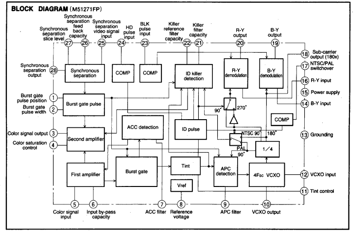
    Then there is more complex analog filters, like this Kramer Composite to YC, but it uses a 390ns obsolete delay line, trimmer coils and only work for PAL.

Then, I got another Kramer Composite to S-video that works with both PAL and NTSC, but it relies on a digital YC separator chip by Motorola (obsolete of course), and requires a subcarrier genlock (PLL+crystals), so not very practical either.

But maybe it’s less critical if you convert the YC to component afterwards, cause at first I was mainly looking to get a proper black and white signal. I was checking my Panasonic AVE5 input circuitry, and the filtering is done using an passive analog filter (like 3 stages encased in a metal case) and it seems that it left a bit of chroma in luma, but then it was sent to a specific IC that does the YC to component conversion.

Here’s an interesting article about this subject https://www.renesas.com/br/ja/www/doc/application-note/an9644.pdf

So a completely analog decoding is sure possible, but seems quite complex, even more if it requires to be PAL/NSTC compatible.

From what I understand, Analog Devices decoder samples the whole CVBS signal at the input (10-bits at 57MHz), and then does all the decoding digitally, allowing for precise comb filtering and such. So maybe that would be a good compromise, allowing to keep an hand on the all process after digitizing, compared to completely integrated decoders that are less flexible.

I’ve build a board with those ADV decoder/encoder, but couldn’t get it to work yet, I’m also learning about I2C communications at the same time so that doesn’t help :sweat_smile:

3 Likes

I2C would be fantastic for an application like this. I’d say potentially asking Lars from LZX how he did the composite and the NTSC/PAL on the Vidiot would be fantastic start on this project.

1 Like

I think the Vidiot only process black and white video, in a similar way as the Cadet Video Input does, you can send colors, but they will be re-encoded at the RGB encoder stage along with the generated subcarrier, so does a bit of rainbow effect as both subcarrier are mixed together (and of course, original video color information will be lost as the signal will probably be blanked), that’s why it’s usually recommended to use a black and white video signal to start with. I guess that beside the sync generator, the Vidiot is mostly analog.

Lars commented recently to someone asking about decoder chips on Video Circuits, and he mentionned the TVP5150, so that’s probably what is used in the Chromagnon, which takes composite/YC/SD Component/HD Component (and maybe more? :stuck_out_tongue:)

i2c not really accessible in the open source fpga workflow. It requires a lot of software overhead, you would have to instantiate a CPU then write a driver to handle it. It looks like analog devices has a lot of other analog to digital encoder options:

I would pick one of the ones with the “pixel bus” ie parallel outputs. ADV7181D looks pretty nice.

The TVP5150 may also be workable, not familiar with the output video standards it references.

The FPGA is sort of a brute force solution. Writing a driver for a two wire interface like i2c (that usually comes for free in microcontrollers) is actually really hard. However devoting 36 pins to a parallel bus from a 381 pin chip with 180 or so gpio pins is easy. Anything that can be done in parallel is better, serialization is hard (all opposite of microcontrollers).

It may also be possible just get tough and write a decoder core for verilog but that sounds like a pretty serious project on its own.

From what I’ve seen on those decoders datasheet, both AD and TI ones needs to be setup using I2C. I’ve been using an arduino for now, could probably be replaced by a small atmega as there is not much register to edit, also depends of what settings needs to be accessible. But true that if everything can be done by the FPGA without a micro that would be better.

Analog decoding would ask for some control to detect the standard, and then switch stuff accordingly to accommodate for the standard differences, could be done by sending extracted sync to the FPGA and control switches I guess, it would solve most of the logic required. So to sum up it requires the following circuit (might be incomplete):

  • Sync extraction (LM1881 or LMH1981)
  • Sync genlock (PLL+VCXO for exemple) to generate a synced clock for the FPGA
  • Subcarrier genlock to be used for the color demodulation stage and pixel clock
  • Composite to YC separation filters (we now have Y)
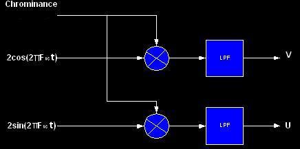
  • C to R-Y/B-Y color demodulator, looks like it can be done by multiplying C with sine and cosine of the genlocked subcarrier

chromademod
(this picture is for a digital implementation, from here)

NTSCDecode

  • Then deinterlacing to get progressive component, which can be done with the FPGA.

There’s is a few open source project for video capture as OSSC or hats for RPi, but most of them relies on an integrated decoder it seems. RPi hats can be quite simple as some ADV chips outputs MIPI CSI-2 which seems to be a digital camera standard, @andrei_jay and @cyberboy666 should have more insight on this.

I was interested by the ADV7280A cause it outputs an 4:2:2 8-bit YCbCr/digital component (ITU-R BT.656), that can easily be interfaced with an encoder like ADV7391 (that will convert the 8-bit back to analog composite/YC/YPbPr). ADV7181D samples at a higher bitrate, not sure what it outputs though, TVP5150 seems to output YCbCr too.

Then, about doing the decoding in digital, I don’t really know much about digital filters so seems rather complex, but looks like a good in-between analog decoding and decoders-on-a-chip.

2 Likes

Is there an advantage to having YCbCr inside the FPGA?

The FPGA verilog code I have played with so far all use an RGB color space, so it is super easy to manipulate each channel, then go out to DVI (like this PMOD). Would also be easy to use an triple DAC (like this adv7123 )then feed an encoder IC like the AD723.

I had initially thought about using the above for output and something like three of these AD9283 high speed ADCs for input.

The scheme for sync extraction and genlock shown above looks doable. A few multipliers and a few digital filters, -not- trivial but definitely doable.

I kind of like the idea of rolling our own instead of using an encoder to allow for non-standard video signals (@andrei_jay was bringing up the ability to tailor it to handle high frequency modulation and corrupted/circuit bent video feeds).

My experience with most chips that offer some sort of parallel bus output (or simple high speed serial interface like I2S or SPI) for FPGA interface is that they have the I2C interface for configuration but it is optional to use it. I’ve set up several different audio ADCs and DACs with the ICE40 and ECP5 this way so far.

There appears to be a an open source MIPI CSI-2 VHDL core. SO it may be possible to use that.

1 Like

No you’re right, it’s better to have RGB inside the FGPA, as it will be easier to work with, however, I don’t know if it’s better to acquire Component with the FPGA and then do the colorspace conversion to RGB in digital, or do the math with op amp in the analog realm and then digitize the converted RGB. I’ve got a small module that I’ll release soon that does Component to RGB conversion in analog, I’ll publish the schematic online but it’s greatly inspired from Linear Tech AN57
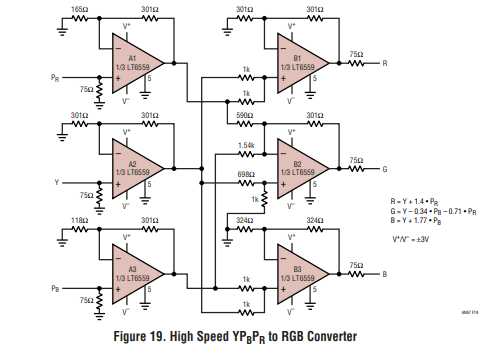
YPbPr2RGB
it just requires some precises resistor values to do the math, but nothing super elaborate, digital conversion might be more precise without the need of 6 hi-speed op amps + passives.
Component is useful in analog cause syncs are embedded in Y and it can be used for luminance based modulation, and it is easily converted to RGB as mentionned before, probably makes less sense in a digital system though, as the clock of the system will probably be derived from the composite signal sync with a PLL and VCXO (as it is done in Cadet Sync Generator), so we only need to sample the active part of the signal.

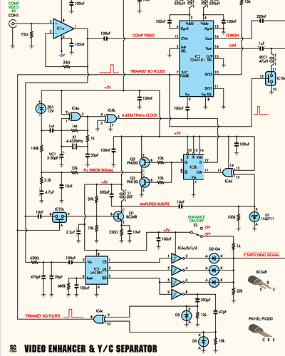
The only thing I’m not sure about on the analog path is the subcarrier genlock, as I wasn’t able to find a VCXO at subcarrier frequency, and it will probably require 2 of them (3.58MHz/4.43MHz), then it can also be done with a crystal oscillator as it is done here.

The full composite video signal is going into the 10nF that is tied to IC10c switch, controlled by the burst output of LM1881, so the switch only opens during burst, which let’s only the reference subcarrier through, then Q1 and associated components amplify the signal a lot to get a square signal. Then amplified bursts are phase compared to the signal generated by X1, and the output (PLL error signal) is used to compensate for this phase difference until both are in phase. Not sure how it will be adapted to NTSC, would probably require a different filter to amplify bursts and a different crystal, I think that’s what the Kramer digital YC separator I’ve posted earlier does: the front NTSC/PAL switch turns switches on and off to get the proper frequency depending on what is required, autodetection of the standard would be fancier :slight_smile:

About re-encoding back to analog afterwards, I was also thinking of doing DAC + RGB encoder, but figure out that it would be a little cheaper to get something like ADV7391, as it will take care of the digital to analog conversion and analog format conversion, only thing is that it can only output one format at a time (either composite, YC or component set through I2C) while going the DAC + analog RGB encoder would probably allow for simultaneous composite/YC/component out without requiring to be set up with I2C.

About non-standard/glitch signals, since the composite to component conversion (analog or digital) heavily rely on proper sync/color ref, I don’t really know how “flexible” it can be, cause from what I get, you need a proper signal at some point to derive all the clocks used by the analog and digital part, so I guess it requires to buffer the signal to be able to keep a portion that is in-spec, so everything continue to run despite the sync or burst being corrupted. It seems that a framebuffer is what’s makes the difference between capture cards that handles glitch well and the ones which does not, also depends of what the designer considered to be an in-spec/out-of-spec signal I suppose.

Anyway, I’ll see what other helpful schematic I can find about analog decoding, looks rather complex but surely doable.

In the case of the ADV chip I’ve tested, I2C isn’t really optional it seems: the chip is turned off by default and needs to be turned on through I2C, same for the clock oscillator (I replaced it at first cause I thought it wasn’t working as nothing was showing on the scope), as long as some “ADI special writes” that are registers that needs to be edited but are not really explained in the datasheet. The idea i had behind the board with the decoder/encoder chip was a converter first (to go from Composite/YC/Component to Composite/YC/Component and also PAL/NTSC conversion), so here it would require to be able to edit the parameters through I2C continuously (at least when a setting is edited).
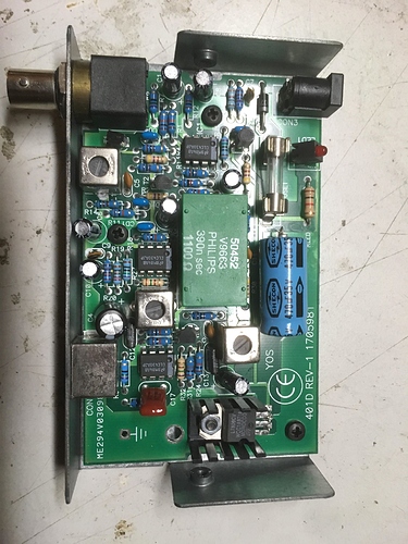
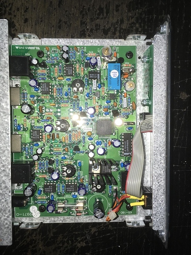
4 Likes

^^ agree with this. will help focus the brainstorming. also some rough ideas around potential cost, part sizes / diy-ablity / interfacing… maybe even some potential applications would be nice.

i dont know much about this in practice, but in my head was always thinking of using fpga in a hybrid circuit (something with both a uC & fpga). i know you can build softcore processes or whatever on em , but when real uC’s are so cheap, seemed to make more sense. for example i picked up a lil dev board like this running a STM32F401 for under $5 , maybe smaller (cheaper) fpga like ICE40s would be suitable if we ofload some interfacing logic to the uC, and use the fpga only for specific video stuff. (also then you get the i2c / whatever control protocols as a bonus)

still though, maybe this video-core stuff needs the fabric speed / multipliers anyways ?

2 Likes

yes i think one of my goals for this is a more general purpose platform for hybrid digital/analog computation and research in general a framebuffer/array of framebuffers is pretty crucial i think for much of what id be interested in exploring as well, not just for video delay/feedback but also for use as potential multichannel framesynchronizer/upscaler/proc amp. another neat thing to think about if we want to work with the component side of things is potentially being able to get down with HD analog signals so we can work with @schaferob s amazing stuff as well as try our own experiments with this mostly unexplored signal. and benefits to YcBcR is that it can be potentially simpler to also capture HDMI signals in that format as well as its not terribly difficult to go from that to RGB or HSV

1 Like

rad!! yeah I was kind of thinking of something between a dev board and a system on module (SOM) with: FPGA, a microcontroller (for i2c config), RAM, video in and out, USB for firmware/gateware updates, and a ton of header pins on it. That would allow anyone to add another PCB with whatever user IO and connectors they desire then sell it or remix it into whatever application they want.

does someone want to start a google doc or git for potential specs?

@BastienL you are totally right about needing the i2c for config.
@cyberboy666 in quantities of 100 or so the ECP5 LFE5U12 is only about $7.50 a piece, with the ice40 at about $6.50. The downsides are that it only comes in BGA packages and requires more power (still a low power device). I think for HD the faster fabric will be necessary and you will definitely need those multipliers for any filtering application.

1 Like

i’m just put orders in for one each of the ulx3s and oragncrab, I wanted to double check with @special_chirp that for a riscv processor is there any need to get an external processor for that? apologize for n00b questions, i’m having a real dickens of a time trying to find sources of info for this kind of stuff thats dumbed down enough for me to get at without hours of google mining

Theoretically you shouldn’t need an external processor. I can’t confirm in practice until I get a softcore running on my orange crab, which is on my desk but I haven’t had time to explore.

The best place for info on these things right now (to the best of my knowledge) is the onebitsquared discord chat. That and github.

The designers of the orange crab, icebreaker, and other fpga boards hang out on that discord channel as well as a number of the principal developers of the open source tool chain. I can send you an invite if you don’t see another obvious way to join. There are a number of people working on video in there, though no one doing video synthesis (as far as I know).

1 Like

Very excited about this discussion, and to hear about these developments in open source tooling! I’ve been away from FPGA programming professionally for several years now, but at one time I worked on some components of a project for H.264 encoding incoming camera feeds (GigE Vision) in real time. At that time I unfortunately had basically no prior experience working with video signals! I worked a little on the processing pipeline (demosaicing, filtering) and with the gigabit interfaces, and on control software for controlling DMA – streaming from Ethernet, to RAM, to cores, back to RAM for verification.

This was all on a Xilinx part (wanna say Virtex-5?) with a hard PowerPC on-die. Later I also worked on some low-power signal processing / data capture applications with some devices by Microsemi (defunct I think) and Altera (bought out by Intel) as well as a bunch of microcontroller programming. However I’ve never really done any board design, I know just enough electronics to read a schematic (sometimes) and break stuff (frequently). I’m excited that a project like this could push me to learn more about that but also moderately filled with dread by the words “very fine-pitch ball grid array”.

Here is some assorted thinking out loud and link dumps from the little bit of research I’ve done since finding this topic (and promptly signing up an account here).

FPGA hardware thoughts

  • “Flagship”-series / hardware-acceleration FPGAs (for Lattice I gather this is the ECP series) will commonly have a lot of “hard” peripherals on the silicon that you can instantiate from verilog - gigabit transcievers, memory controllers, some have complete processors on-die like the Memory Palace’s XC7Z010 SoC. Gigabit transcievers seem potentially useful for working with signals like HDMI, Ethernet, USB, even PCIe – seems awesome to me to have some high speed digital interface with a PC. This can be accompanied by a lot of complexity with drivers, etc. but seems like a really interesting possibility.

  • Many parts also have a DDR SDRAM interface, which can be very valuable for things like framebuffer applications, or if you want a CPU core on the FPGA. The ECP series chips have this.

  • I2C peripherals or USARTs with I2C/SPI modes are also sometimes available in silicon, depending on what application your FPGA targets. Looks like Lattice iCE chips have this. For either of these you can also potentially use / adapt some existing cores – the Lattice I2C controller reference design mentions it’s based on this one from opencores.org.

  • Lattice CrossLink devices have I2C hardware as well as MIPI D-PHYs which could be used for the CSI-2 camera interface. This looks to be a family of smaller FPGAs intended for video switching applications, but they have fewer fabric resources than the ECP chips, and the open source toolchain doesn’t support them at present.

  • I found this page from Lattice describing a framebuffer core which interfaces with a memory controller to talk to SDRAM, which is used for the actual frame storage. For the iCE series this is a big chunk of available fabric and for some chips might not leave enough to also have a CPU core if you wanted one.

  • Speaking of fabric resources, the closer you get to using the whole chip, the harder it often gets to route your design / meet timing requirements. In some cases you can use a floorplanning tool to manually provide placement hints to alleviate this, but this kind of thing can be challenging to deal with due to the constraints imposed by the PCB design and allowed chip I/O assignments. It’s worth keeping this in mind when deciding on a chip and estimating how much fabric you’re going to need.

  • Having a CPU, hard or in fabric, on-chip can be really nice for basically having programmable fast access to registers for controlling peripherals and stuff, even if a bunch of higher-level “application” type stuff is handled by a dedicated MCU chip. Serial communication and controlling peripherals all in verilog is a lot of work, and interesting but not near as enjoyable a use of FPGA coding time as cooking up high speed image processing pipelines.

  • Once upon a time, Xilinx sold analog video I/O expansion boards for their high end dev kits. Here is the user guide and the block diagram. It appears to have supported a load of different interfaces. Uses the ADV7403 decoder, which seems like a neat chip, I don’t know if there are more recent models with this kind of feature set.

Requirements and design thoughts

  • Accepting glitchy input is an interesting problem. I don’t know if anyone has heard anything about how well LZX TBC2 can tolerate glitchy composite inputs? Guess we’ll have to see once they’re in the wild. Might also be interesting to look into what hardware is used for the 1V I/O on Orion modules. One thing that’s interesting about decoding in fabric (if possible) is that any decoding you don’t need for some application, you can use those resources for something else.

  • On the video compression project we converted to YUV as soon as possible and stayed there – H.264 requires it, but I believe we were also usually chroma subsampling to save FPGA resources.

  • Interested in scripting and high-level synthesis thoughts, and in general the question: how should typical ‘user space’ for the end device work? How would you like to design a “patch” for your ideal such device? What kinds of things would you want to explore that aren’t currently possible / are difficult in your current workflow? I feel like there are so many incredible tools for video around and emerging that I need to think on that last one some.

That is probably more than enough babbling out of me! I reckon I need to do some more research on all these different development board options and stuff. Super glad to have found this topic and forum!

3 Likes

Hi! Awesome to have you on the forum! Sounds like you have a ton of experience.

Just a comment on the FPGA hardware thoughts. I’ve been a huge fan of the recent open source yosys/nextpnr/project trellis tool flow (which is why the lattice parts are brought up). One of the downsides to this is that you have no vendor IP, and most hard IP is inaccessible (ie no access to built in I2c controllers).

The way most people make up for that is Litex.

It’s sort of an open-source SoC builder that includes ethernet, DDR3 controllers, HMDI, softcore CPUs etc. You assemble these prebuilt cores using a python script and assign ports and registers so they can connect to whatever you are instantiating in the fabric. (For example the orangecrab board uses this to access its DDR3 ram).

lots of other good ideas and questions in there that I don’t have answers to :slight_smile:

1 Like

Awesome, I was wondering about this. I’m pretty new to the wealth of open source stuff available here, I need to do a lot more reading on this and trying stuff out! Great to see there is a logic analyzer here.

I’ve just found this awesome project which uses an output pin and an LVDS input on the FPGA plus a simple addon circuit to create a sigma-delta ADC for capturing an RGB+sync analog signal. So rad! I have this exact dev board or something really close to it, if I can manage to get an old enough version of the Altera design software to run I may have to dust it off and check this thing out. The github page notes that it has some noise problems and the original source video is pretty low-spec but what a cool proof of concept. Seems like maybe an easy way to get some kind of analog video input by making a hat for one of these open source boards. Also some cool tricks here for improving the DAC resolution.

Just popping in to this conversation. A lot of really good ideas and stuff coming around. To spark the conversation on describing a core system, I guess it’d be good to figure out categories of features, and then start listing and quantifying.

In terms of system access points, it would theoretically have, at a minimum, input channels, output channels, and input modulation, and some forms of feedback, to create something interesting to play with.

I see mentions of LZX’s modules a few times, but haven’t seen Gieskes’ 3trinsRGB+1C mentioned, which also had an interesting feature set.

For signal inputs, I’d want to play with at least two, and be able to perform arithmetic operations composing them with a variety of blend modes. For modulation, it may be nice to access, distort, or replace sync signals. Chromakeying operations would also allow for other explorations.

I’m speaking very much as if this were a fully realized video synthesis piece of equipment, but I think looking at end use cases may improve an early description of the core architecture, in order to realize where we may want to break out control lines, and of what the overall system path would comprise.

I’m just beginning with a homemade video playground, and look forward to seeing how this project develops.

2 Likes

I think there are a couple of interesting possible use cases to explore, which might call for different types of I/O. But one thing I think is great about FPGA platforms is they don’t have to be all things at once, you can use pmods or other kinds of add-on boards to extend the hardware in a modular way, and reconfigure your SoC to only include the logic you actually need for a particular “gateware app”. On the other hand, doing video I/O on a different board can cause difficulties with the bandwidths needed for high resolutions, depending on the interconnect.

Here are some categories I’ve been thinking about, loosely defined and with an understanding that many features make sense in other categories besides the ones they’re listed under. “Prior art” sections are also just scratching the surface of the many years of incredible work many people have put into FPGA tools for video. Mainly just hoping to write some thoughts down and share some research!

Pattern generator / video oscillator

Hardware needs

  • RCA genlock input
  • I can see most types of output being useful here, depending on what you’re working with. VGA and HDMI output are the most readily accessible - a VGA-to-minijack module or adapter might be the best way to support integrating with a modular system.
  • CV input? There are a number of designs floating around for DIN MIDI pmods, or some type of USB control from a computer could also work for “animation” controls.

Prior art

  • Milkymist looks quite awesome. The hardware is no longer available but the group behind this continues to be very involved in open source toolchain development and FPGA hacking – after all “Migen” is short for “Milkymist generator”, see e.g. a framebuffer core here.
  • LZX Fortress and Diver modules are prominent programmable-logic based devices and what I think it makes sense to be compatible with, as far as sync connections and voltage levels and stuff, though I personally would be fine with such a thing not actually fitting in a Eurorack case.
  • FPGAWhack is a cool project which lets you compile C expressions to instructions for a pixel processing unit, which I think is a super interesting idea to explore.
  • A lot of retrocomputing stuff on FPGAs I think is also a really valuable resource, for example I recently got glitchNES running on this NES implementation, which includes audio and picture processors, using an iCEbreaker board and a VGA pmod, you can imagine adding CV or midi input or other Ming Mecca type features to such a thing. Tons of cool stuff at FPGA Arcade, as one of many examples.
Video processor / effect

Hardware needs

  • Analog video I/O
  • Multiple outputs, feedback patching considerations. TBC?
  • Enough RAM for framebuffers

Prior art

  • LZX Memory Palace is an RGBA framebuffer for patching with LZX video synthesizers.
  • Here is an interesting application converting VGA input into ASCII art on a terminal in real time. (source code)
  • The NeTV2 is focused on modifying video content in real time and seems like a very nice platform for digital video – two HDMI inputs, connects to a Raspi. hdmi2usb can be run on this board by using an add-on board to use the PCIe connector for USB. They have a repo for discussing the many applications this kind of platform could have if it were not illegal to circumvent DRM on legally owned video content under the DMCA. The board’s creator is part of an EFF first amendment lawsuit challenging this provision in the DMCA.
  • The Open Source Scan Converter is a platform for rescaling older video game consoles to output HDMI to newer displays and equipment. It supports several analog input options, using a TVP7002 video ADC chip.
Capture / utility

Hardware needs

  • Act as a USB video device
  • HDMI and analog input attachments
  • Mass storage attachment
  • HDMI preview out

Prior art

  • hdmi2usb is a long running project that’s overlapped with a lot of open source toolchain development. It has a focus on teleconferencing and live event streaming / recording. It seems the board they designed, the Numato Opsis, is no longer available.
  • The ULX3S board seems maybe promising here? Looks like there is a GPDI input pmod, an SD card slot, and possibly high speed USB capabilities? At some point? I’m not certain what the status is on that or if it’s achievable with this hardware.
Some general considerations and thoughts
  • RAM specs are an important thing to consider for selecting an FPGA board or system-on-module, particularly for framebuffer applications. You can put more memory on expansion boards but it’ll be much slower. As a reference point the LZX Memory Palace uses this SoM which has 512MB DDR3.
  • High speed USB also imposes some constraints, historically this has required a USB transciever chip but if I understand right people are starting to do this now with just ESD protection between the USB connector and the FPGA?
  • Options for different kinds of expansion boards seem like an important factor for board selection / design since I think there are really a lot of different video I/O requirements for different applications. There is a CSI pmod design that I believe was designed to work with the Raspi camera, perhaps this could also be used with the PiCapture boards?

ULX3S boards are expected to start shipping in another week or so and I’m super excited! It turns out I accidentally ordered 2 of the pmod sets (one each of dual USB, HDMI, and OV7670 camera) – if you got or are getting a ULX3S, DM me and I can send you the spares once they show up! From looking at the repo I believe these have an additional non-standard pair of pins designed for the ULX3S and are not pmods you could necessarily connect to other FPGA boards.

3 Likes