Nearly there with bugfixing the Quarterizer. Here’s a quick and dirty mobile phone demo of basic use as a four level quantiser. Sorry it’s out of focus ![]()
5 Likes
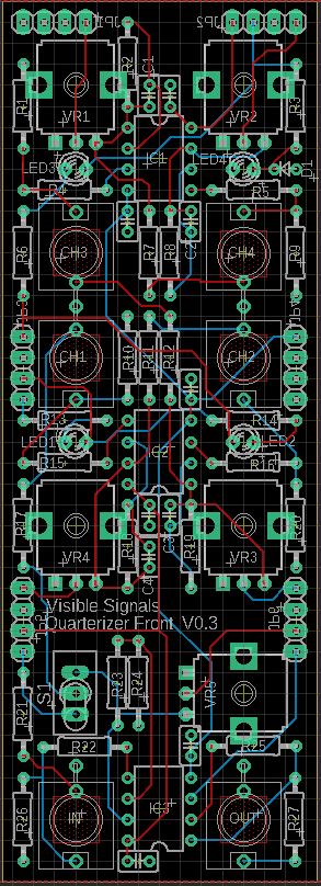
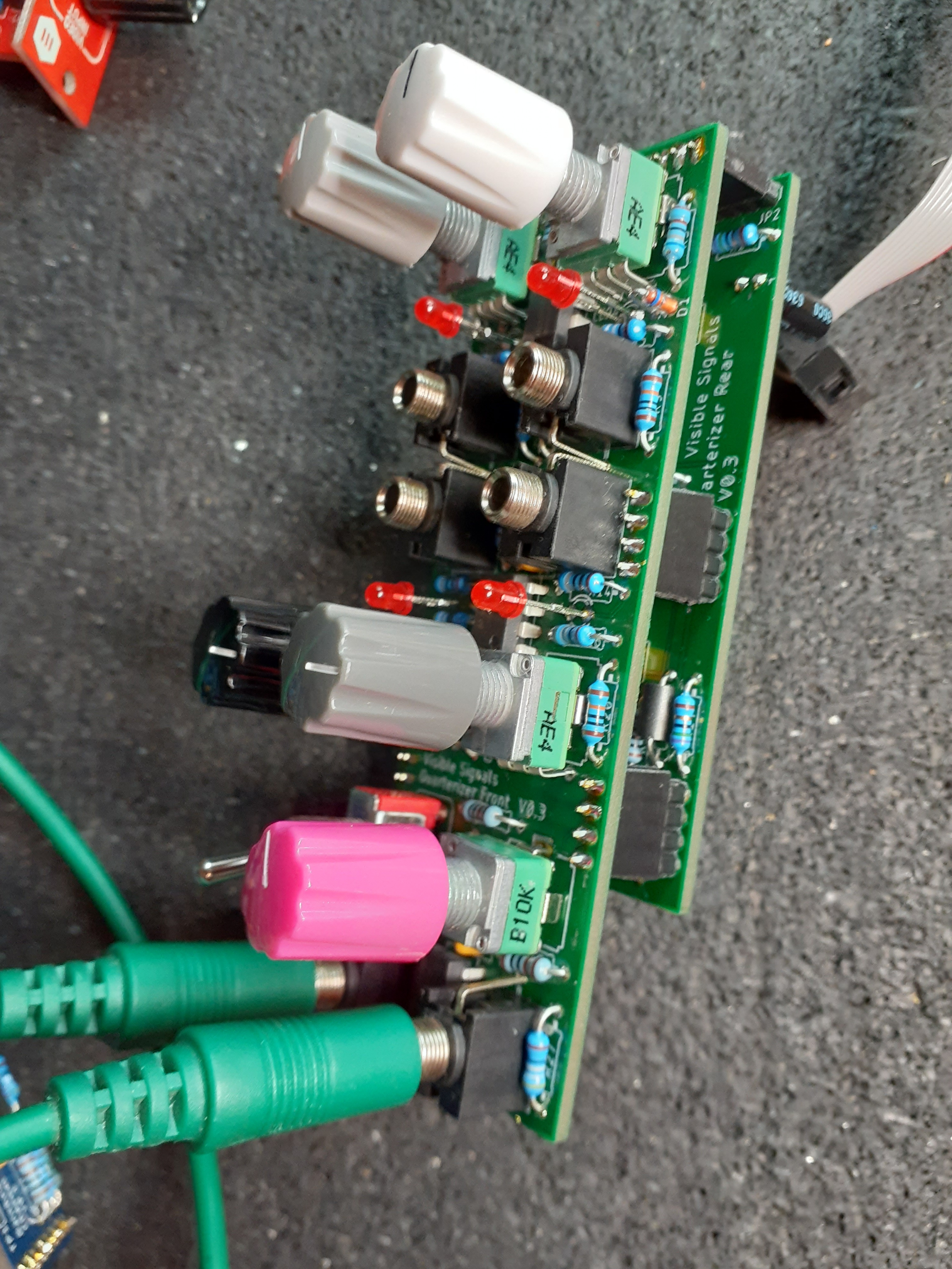
Quarterizer update: for best results I decided I needed to redo the PCB layout to reduce the normalisation signal paths. This meant re-routing both of the parallel PCBs… a lot of effort! 
Here’s the corresponding new panel design, with the individual input sockets now clustered in the middle. I’ve also added a switch to control the normalisation path on the first input, so switching between the IN signal (for image munging) and +1V (for luma quantisation and sequencing tasks) is super-easy. I’d love to know what people think.
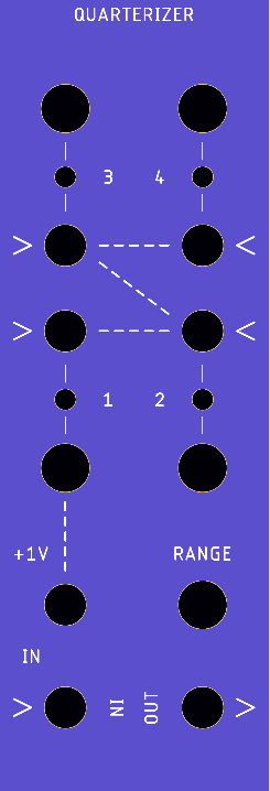
The large holes are pots/knobs, the middle-sized ones are sockets (other than the one directly above the IN socket which is the +1/IN switch) and the smallest ones are LEDs. I also added normalisation signal flow graphics on the panel using dotted lines, what do people think?
Sorry about the colour from the gerber viewer, for some reason it’s much paler than the real panels are.
For reference, here’s the old version:
All seem like improvements to me.
Only comments I have are minor cosmetic quibbles. First, it looks weird to me to have “IN” and “OUT” aligned in opposite ways (I know that’s your standard across all modules, but here especially it reads as “NI / OUT”). Second, I wonder if “RANGE” should possibly be nudged upwards a tiny bit (looks awkwardly close to knob in v1)?
1 Like
I hear ya on the NI/OUT thing. The design rule is “text above the thing to which it refers” - even if you have to turn the module sideways to work out which way is up. I struggled waaay too much with that, trying to find a consistent design ethic that worked across all modules, and I know it sometimes looks a bit unusual like in this case. I’m still not completely happy with the RGB Matrix Combo panel either, but the V0.2 for production is a little better than the one that’s on the site at the moment. When I started out making video modules I really wanted to stay away from eurorack because it’s just so darn squishy, but you know how it is - VHS vs. BETA.
Now that the Range knob has moved to an edge position and isn’t in the centre any more that means it should have an edge label too - like this:
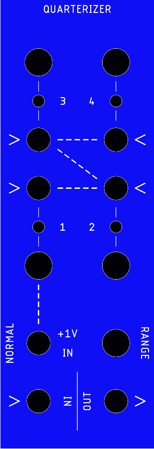
Some other changes there too. The vertical line between IN and OUT calls out to the Combo panel, so it’s legit.
1 Like
Since I mentioned it, here’s the latest Combo panel design:

One day I’ll fix the Output socket alignment along the bottom

2 Likes
Great progress, these all seem like improvements to me.
The switched 1V/main input normalization is a better workflow since it’d otherwise expend a DC offset generating module when luma quantization / sequencing is a very apparent use for this module.
I find it easier to navigate modules when the pots/switches and jacks are on opposing sides of the panel. Grouping the individual input pots feels less crowded than the original layout but the spacing looks very manageable in this update.
Horizontal text is usually easier to read but I get your approach which seems like its aiming to accommodate narrower HP widths. It’s impressive you’ve gotten this down to 8HP for feature to HP ratio. You have an input on the left and an output on the right which I can definitely live with.
1 Like
Thanks! Yes it’s certainly a tight squeeze in 8HP and has taken a few iterations, hopefully getting better each time. The front panel board sure has a lot going on but I got it to all fit in the end!
The way I see it, I think generally when you’re using the individual inputs you’ll mostly set and forget the knobs (either as individual signal level controls or as CV presets) and when you’re tweaking them you’re more likely to be doing so because you’re processing the same input video signal on all inputs. But regardless I’ve tried to optimise the space available as best I can, and the LEDs between the knobs and sockets help pad it out.
2 Likes
For what it’s worth, in general, I do respond positively to the sort of quiet, “logical” aesthetic of your panels — even if a few of the individual decisions aren’t necessarily what I would consider most functional. They have a classic “DIY modular synth” look to them that I appreciate.
3 Likes
It’s definitely time for another Quarterizer update ![]()
I had another prototype PCB made up with workarounds for the op-amp ringing problem and a couple of other minor issues… and it turned out the ringing still happened, in certain circumstances. After even more debugging, I finally identified that the main contributing factor was the normalled ‘chaining’ of channel inputs. So I worked out a way to fix that (changed some resistors and added a few extra) and happily the issue went away.
However, when I put it in my main video eurorack case and tried it out the results were… disappointing. Although it basically works as it should, when processing pixel-rate video the LM339 and ADG333A are just not fast enough and the image ends up unacceptably blurred.
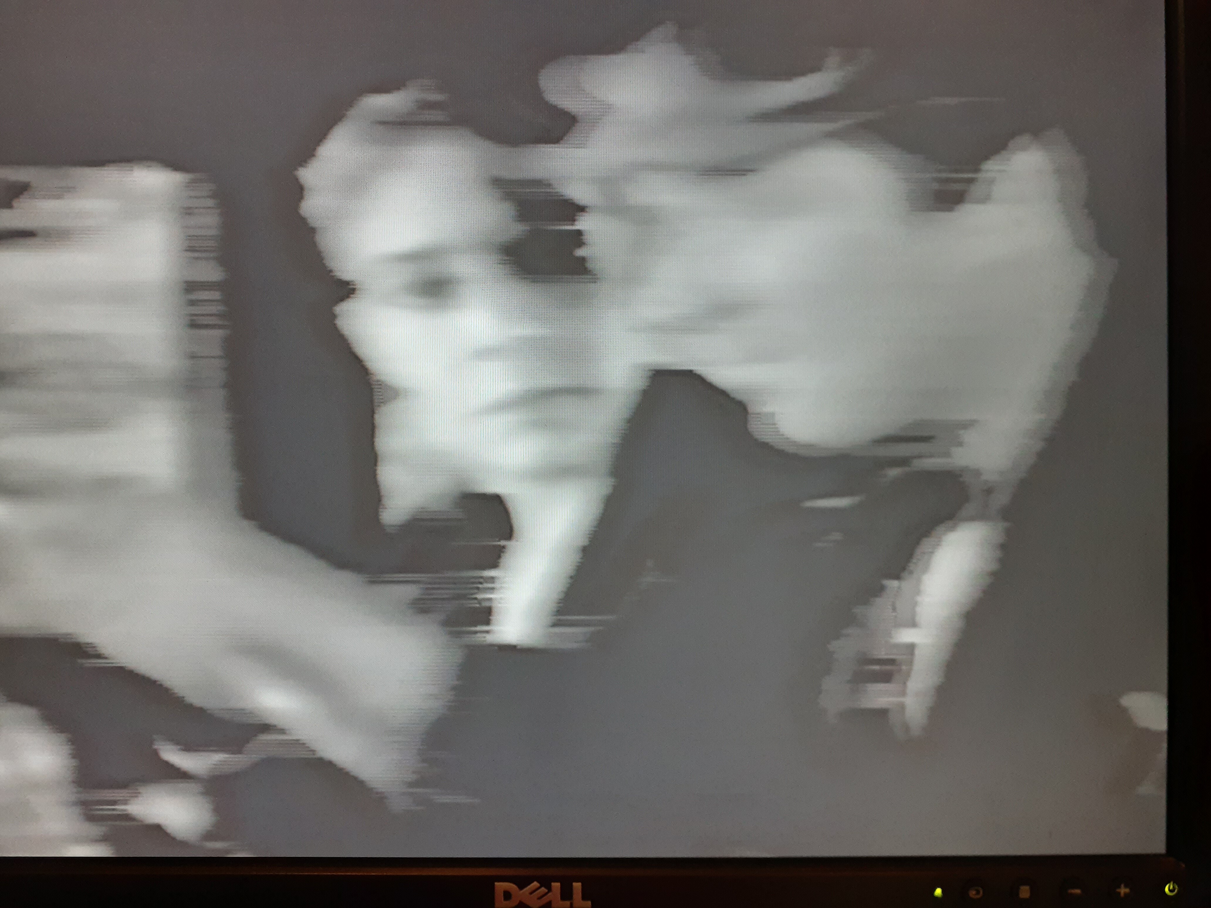
Video: Smeary pixels from the Quarterizer prototype - YouTube
Secondly, because the AD333A is break-before-make the output signal drops to 0V for ~10ns during input channel transition periods, which is occasionally visible in a bright image as black spots. Also, the signal overshoots slightly on the transition edges (but I can’t actually tell if this is really visible or not, due to the image blurring).
(Picture shows worst-case bright horizontal lines from a Cadet X VCO)
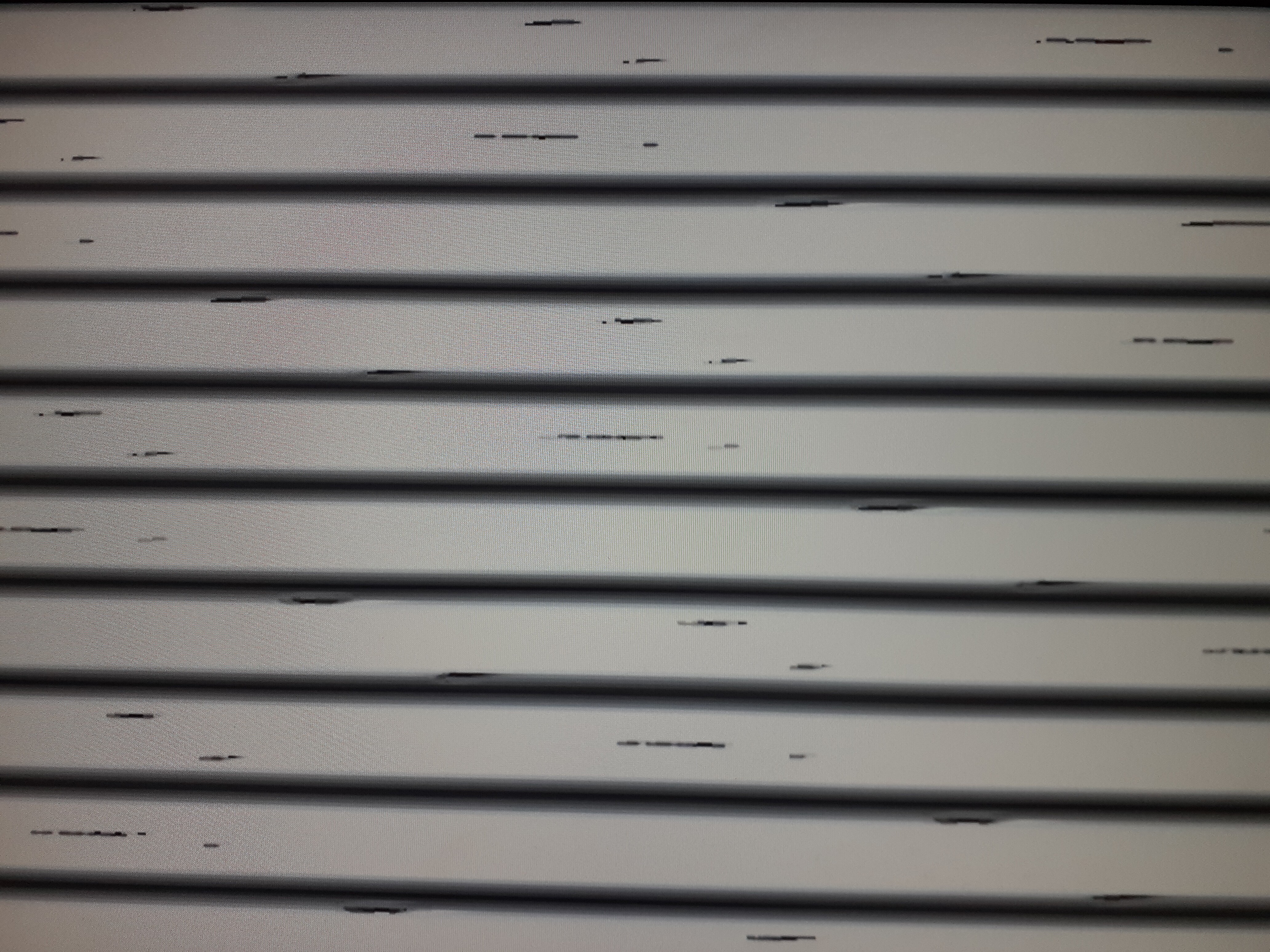
Video: Overexposed Quarterizer prototype video shows the channel transistion 0V (black) glitch - YouTube
Here’s a scope picture showing the 0V break and overshoot between input channels (the input is a Cadet X VCO triangle wave):
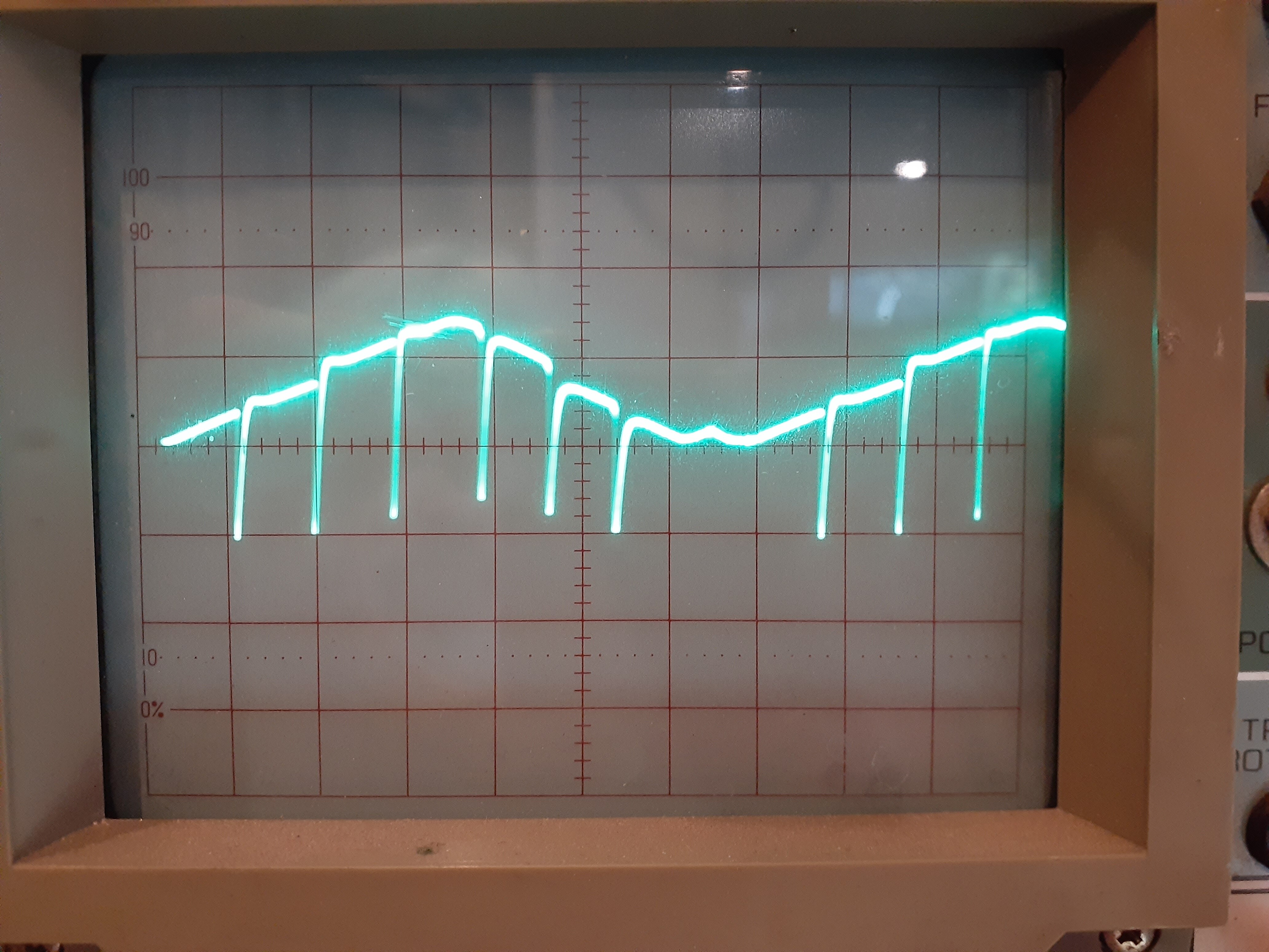
Finally here’s an example showing the poor signal bandwidth when processing high frequency vertical lines from a Cadet X VCO - you can also see as I adjust a couple of the input channel attenuators that at higher frequencies the 10ns 0V break really is quite unacceptable. That’s supposed to be a triangle waveform!
Video: Quarterizer prototype - the scope reveals all - YouTube
I don’t want to put a sub-standard module out there so I’m going to refund the cost of the Quarterizer to everyone who ordered one and keep working on it. Basically I need to change the core to use faster comparators and a better signal switcher IC.
I am sorry for this - the fault is all mine for not testing the initial design extensively enough. I’ll keep working on it and let everyone know once I have a version that is absolutely 100% verified - with demo videos and confirmation from some independent beta testers.
3 Likes
Thanks for the detailed post regarding the problems with your Quarterizer module @VisibleSignals
How has it developed since you last posted? Hopefully positive but maybe sourcing components has become problematic with delays in deliveries & such.
Hope you’re doing fine, health is definitely the most important thing in all our lives.
Hi! Quarterizer was an important learning experience for me:
- Don’t announce too soon
- You always have more to learn so don’t bite off too much up front
- Always get other people to beta test before you release!
But the nicest learning was just how supportive the video DIY community is. Despite announcing and taking some peoples’ money back in October, not one person has complained that it took several months to get everything organised and all the pre-orders shipped, or even that it is taking ages for the boards to travel around the world from Australia. I am humbled by how understanding and patient everyone has been.
In terms of the future for the Quarterizer, I am working on a couple of simpler modules which break its functionality down into separate, smaller pieces. I will release them first, and then revisit the full Quarterizer design itself and put it out as well. I also finally took the plunge and bought a really good scope (Rigol DS1104Z 100MHz 4 ch) to replace my old 10MHz dual channel analog clunker, which is making a world of difference.
I also have some other designs that are in the prototyping stage that I’m planning to have ready around February.
3 Likes
Shit happens but I’m glad to read that you’ve found some solutions & breaking the module up is a good work around for now. I’m really curious as to your other WIPs, any exclusive hints for the scanlines participants? 
No exclusive hints, sorry That’s what I meant by “don’t announce too soon”… all designs must be built and confirmed as working by my beta testers first.
1 Like
Truth, I really wasn’t thinking when I wrote 
Ha ha, it’s all good
1 Like