Using monostable to generate blanking pulse for composite video

@BastienL (coz i know you are working on composite-sync-gen):

lets say i want to generate a pulse for the duration of a pal blanking period. i have the csync output from lm1881 (sync seperator ic) which is the a part in this diagram:

but i want my pulse to be the whole blanking, (a+b here i think ?)

so i want to use a monostable cd4538 to set the length of the pulse, starting from csync, to be a fixed 12.04us.

the monostable uses an external resistor and capacitor to set the pulse length (T):

where T = Rx + Cx edit I meant: T = Rx * Cx

from the datasheet:

so im guessing if i used Cx = 0.001uF and Rx = 20Kohm trimpot, i can set the pot to just over halfway, which should be around 12Kohm x 0.001uF = 0.012ms = 12us

how does that sound ? is this how you would do it ?

1 Like

Hey @cyberboy666

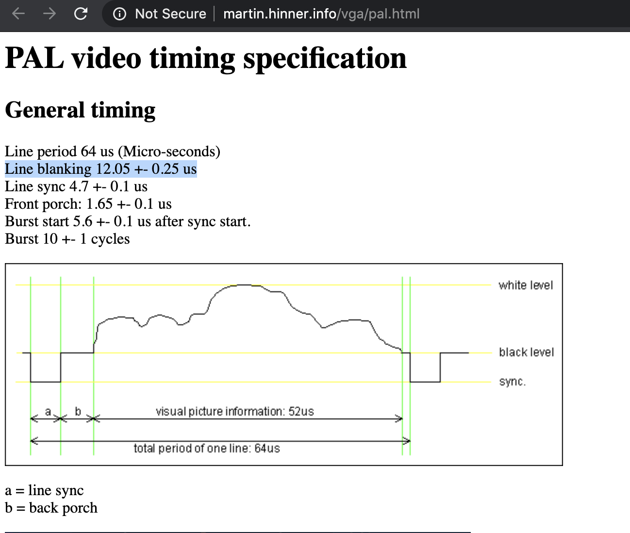
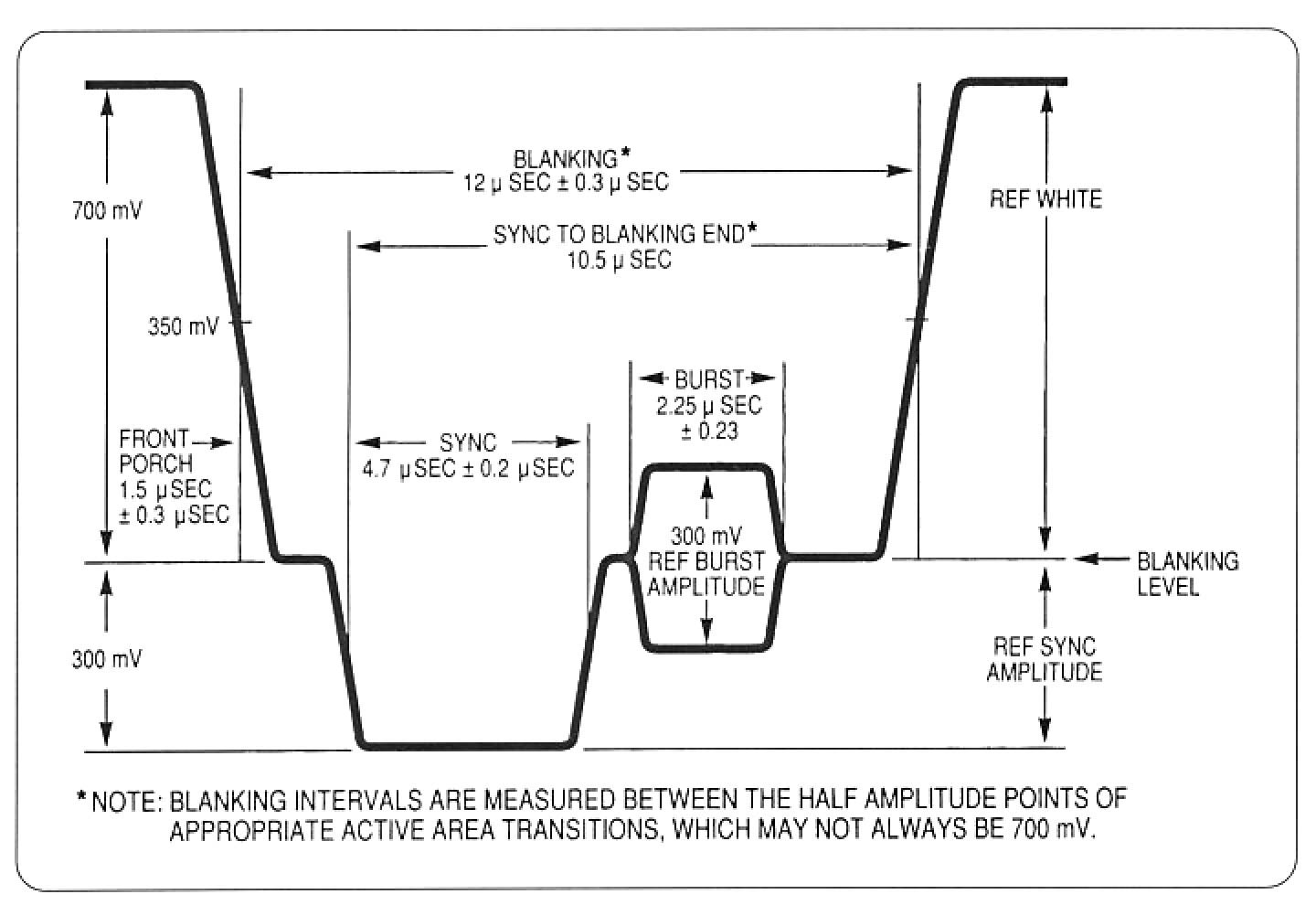
Here is a little bit more detailed diagram for blanking:

As you can see it is composed of the front porch + “sync to end blanking” (which itself goes from beginning of sync to end of the backporch.)
Using a monostable with csync, you can easily produce the 10.5μs “sync to end blanking”, the front porch is a bit more tricky to get, but it seems that you can get away without it.
(Still waiting for my sync gen + RGB encoder board to do more tests).

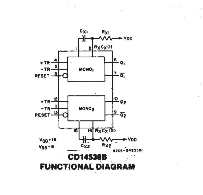
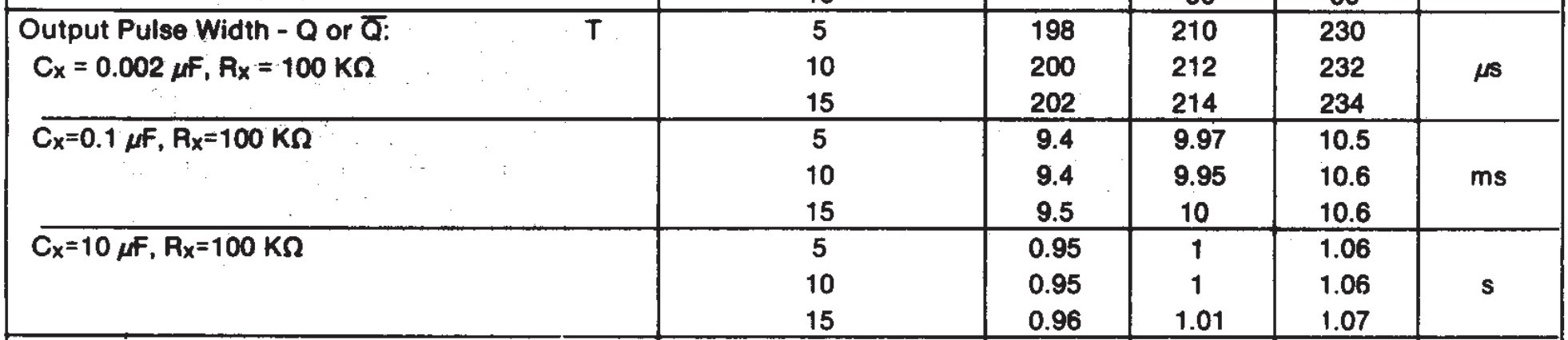
Actually, the CD4538 timing is calculated as follow:

T = 0.7 * Rx * Cx

(couldn’t find it in the original CD4538 datasheet, found it the 74HC4538 (low power/high speed version of the CD part) http://www.farnell.com/datasheets/2030204.pdf)
(also, all monostables don’t have the same formula, NE555 is T = 1.1 * Rx * Cx for example)

When choosing your RC values, it’s important to note that, you can choose almost any capacitor value, however, there is a minimum resistance to have (learned it the hard way by burning a dozen of NE555 while I was using only a potentiometer for R lol).
So it is a good practice to put a resistor between your potentiometer and V+. The 4538 requires a minimum of 2K under 5V, so I would advise to put a 2.2K resistor between V+ and your pot, so whenever your pot is at 0ohm, there will still be the 2.2k resistor.

So the “exact” value for T = 10.5μs, Cx = 0.001uF would be Rx = 15K (I put quotes around exact as Cx and Rx will always be within some tolerancies, that’s why a pot makes sense here).

So yeah something like this should work (forgot to put Csync on pin 5 / B input).

Of course, if you’re generating the sync using a micro, you could generate the blanking from there more precisely/easily, but if you want to generate blanking from an external video signal, you’ll need to have your sync generator genlocked to the external signal in order to get blanking. That’s why the monostable is a good solution here when the sync gen doesn’t have genlock, so you can switch between internal/external sync, the pulse length will be determined by the monostable afterward.

Hope that helps, will report more about this once I’ve played a bit more with the sync gen.

Edit: a trimmer is useful also if you want to set the right pulse width for PAL or NTSC. I didn’t use a potentiometer on the board I made, I’ll see if I can find a good “in-between” value that would work for both standard, cause if I keep a 10.5μs timing with a NTSC signal, it might result in a black bar on the left of the screen.

Edit2: looks like there’s more differences between CD14538 and 74HC4538 than just the supply voltage/propagation delays, looks like the older part pulse timing is calculated with something around T = Rx * Cx, and minimum R value is 4k.
So it will depend of the part you use, the CD14538 is intended for voltage up to 20V, whereas the 74HC4538 is rated for 5V max and has smaller propagation delays.

2 Likes

Sometimes, a video is better than words, thanks to the awesome Rob Schafer!

2 Likes

Very cool. Thanks. Next is Vertical blanking. The same technique doesn’t work very well. Another video (maybe I can mount another lesson) will show the problem and one solution.

2 Likes

@BastienL i ended up ordering some of the 74HC4538 in the end. makes sense to use more modern / lower v rated parts. will report back how it goes.

@schaferob hi Rob ! nice to see you are here. been really enjoying the tutorials you are posting to youtube. somebody else to bug ask about details of analog video circuity besides @BastienL :wink:

you should start a thread with your videos at some point

Hello.I’m still feeling my way here. (Sometimes I get confused by simple things if they’re unfamiliar.)

So I wrote an introduction about me. Not sure how to post it or where/how to contribute my jpegs and pdfs.

Hi @schaferob, awesome to have you here.

About your pdfs/jpegs, you can upload them to this thread if they’re relevant (just seen your Blanking Generator video/schematic on VC which is 1000% relevant here :slight_smile: )

Else, you can create new topics from the website mainpage and you could have a video + related documents on the same post, one for each of your lesson for example (just an idea, it would make them a bit easier to find than in the middle of a thread like this one).

And about the upload specifically, you can drag-and-drop your files in the text area or use the upload button above, Youtube videos are embedded if you paste the link (I think?)

1 Like

@schaferob thanks a lot for your videos covering these subjects - it feels like i have been trying to digest this information for ages and its finally starting to make sense (also big thanks to @BastienL for this )

i had two questions while watching the videos. (one i think i may have answered myself):

  • the schematic you draw shows two opamps - one for gain and another for inverting - i wondered why you didnt just use a single opamp to perform bother inversion and gain ? i think this is because you want to use the non-inverted gained signal elsewhere to invert the colour burst ?
  • secondly - what would happen/how would it look if the active video is inverted but the colour burst stays the same ?

btw feel free to start a new thread about your videos here also - having a dedicated place to talk about them would be cool too. :slight_smile:

Excellent questions!
That first opamp does a couple of things. First, it’s completing the soft clamp circuit. That circuit won’t work if it’s looking into a 1k resistor of an inverting amp. The resistor that pulls down on the diode is typically 1 megOhm. Because I have to use the video to go a couple of places I like to buffer it. It’s going to feed the comparator in the blanking/burst section. It’s also going to be an input to the 74HC4051. That switch will perform better if all three its inputs are buffered. If we don’t invert the burst the color will go negative. That’s not bad, it’s just boring (to me). All the faces go blue. Hey, that can be a cool effect (pun not intended) effect too.

3 Likes

thanks for the tips -> and for the record i see all my questions are also answered in the next video here:

really nice project, i look forward to trying it out myself.

@schaferob , not sure if it is something you are interested in at all (i see your loyalty to the breadboard !) but if i was to create some small pcbs to experiment with these for myself i could also share the files with you or with everyone under an open-source-hardware licence ?

as an educational supplement to the resources you have already created , could be useful for running workshops or for people interested in cad designing aswell etc…

4 Likes

(Me and my damn breadboards!!)
I’d be flattered and delighted if you wanted to lay out some of my circuitry. Do you think the “Luminance/Chroma Inverter” would be the right circuit to do? (I can imagine making the clamped video, blanking and burst signals available for other experimentation.)

I don’t feel like the “Two Comparator Effect” is fun enough to build. (I could be talked out of that, though. Adding one more comparator would add a grey level to the black and white.)

The upcoming circuit is the one I’d want to own, but it’s more complicated and more expensive. It’s a complete three level colorizer capable of standard definition or HD. However, it outputs component video not composite (or S) so an additional cost will be involved if folks want to do standard def with it. I’m hoping to draw some folks up into the HD realm with it.

What are your thoughts?

2 Likes

I really admire your breadboarding @schaferob! I do test some small circuit/ideas on breadboard, but I think I’m missing your meticulousness and once the circuit gets a bit bigger, I’m often spending a bit too much time finding bad connections.

Anyway, I think even the smaller circuits would be interesting for people to build, there is not that much composite video processors examples around, and the documentation you make of it with your videos is super helpful to understand.

@cyberboy666 let me know if I can help, wanted to try a PAL adaptation of the “Two Comparator Effect” as we discussed about this on Rob’s post on Video Circuit (basically inverting the subcarrier every odd line)

@schaferob

Yes ! I was imagining exposing these values also for future experiments.

There really is not much out there for beginner diy video circuits and I agree that everything has its place - including the super simple stuff -> from my observations it is the circuits you might think are too simple to be useful that people have the most fun with (not sure if you have seen the crazy and creative expansions of the ‘dirty mixer’ idea. Similar with the many vga hacks out there )

Adding an extra gray level would def be nice to spice it up a bit !

And yes ! a hd circuit would be very interesting and useful especially for intermediate builders where the slightly higher cost/complexity is totally worth it.

From my perspective the more the merrier - small/medium designs can be routed in an afternoon usually (maybe like @BastienL I’m more fluent with software than breadboards :sweat_smile: ) I am excited to contribute to these invaluable community resources however I can.

I would use kicad since it is open-source unless you had another preference - and can send you the files or host them on my GitHub , however you prefer.

@BastienL yes would be fun collaborate. Time to dust off your kicad skills ?

Maybe I will start a new thread to talk about this little operation :wink:

1 Like

So… is this topic “technical questions/help” the best place to put my stuff? I’m thinking URLs to my “Lessons” and auxiliary vids. And schematics. I had this pompous notion I’d get my own (don’t know what you call ‘em) super topics. Forgive me.

3 Likes

:laughing: they are called categories here. i just created a new one for you called circuit lessons - we can update them also to fit better (if no one else posts there i can rename it to robs circuit lessons lol)

2 Likes

hell yeah you can have your own Super Topic @schaferob !

1 Like