Whiteboard schoolhouse companion circuits

Excellent job. Ah, the whole Q8/Q9 active low/high confusion. Q8 falls when Q9 rises. so either will work. Q8 to active low, or Q9 to active high. Whoops. Or do I have it off by one? If Q8 falls after 256, Q9 should rise. (I just read your line about Q9 not having anything on it. Hmm.) Sorry for the confusion.

Definitely different values for PAL and NTSC.The 4040 was just to get over closer so it’s not a one-shot trying to be stable enough all the way down the page. It turns out not to be “perfect” vertical blanking because the two field aren’t the same. I get crazier about this up at 1080i 'cuz it’s not uncommon to see all the way to the edge up there.

The fact that the CRT looks better than the LCD makes me think the LCD sync pickoff isn’t as “friendly.” My circuit soft-clamps the incoming video and uses it’s sync. It doesn’t clean up that sync at all.

About triggering your scope. You should be able to use signals from the circuit to trigger the scope. Maybe add test points on the board? (A case could be made for a “TV Trigger” circuit you’d use with the scope.)

Just and idea.

Don’t know how far you want to go with it, but a possible mod to the circuit would add some delay to the burst which would give shifts other than 180 degrees. Somebody mentioned that’d be good for feedback. I had an idea to use the other control pin of the 4051 for that. Then repeating the inputs (I’m not saying this very clearly) except suppling a delayed burst. I’d dig up some little inductors to help make the delay but just some resistor-capacitor combo should do.

Since the signal looks good on the CRT I’m not sure decoupling will help. (It never hurts!!) Have you looked at the +5 on the board? If it’s real quiet and clean decoupling won’t necessarily help.

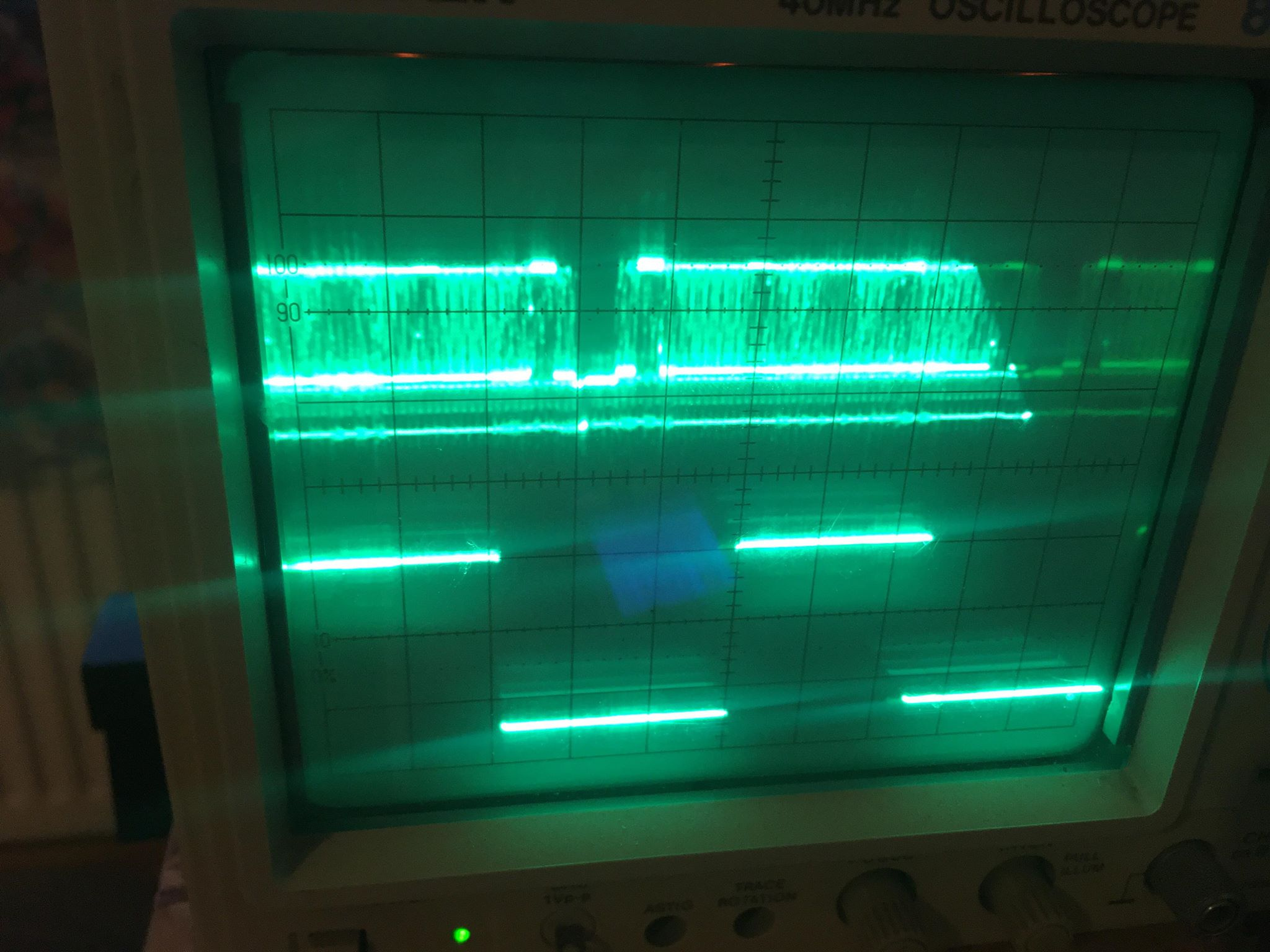
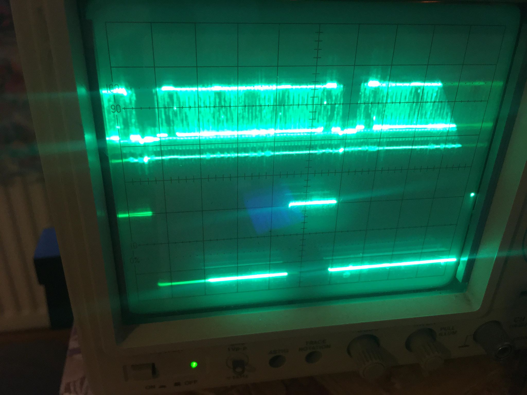
One last question: Were you able to see the horizontal blanking well enough to set the H delays?

Thanks again for putting all this great work into my circuit.

1 Like

no problem - and thanks so much for sharing - i am learning so much by building these !

ahh. ofcourse, yes i understand now that can use rising or falling edge depending on which counter output. yes i think then your schematic is off by one (or two if keeping the falling edge?)

atleast from my test this is a picture of Q7 (where one-shot should trigger on falling edge)

and this is Q8 (where one-shot should trigger on rising edge)

will play around with getting the vblanking in place for pal and report back…

and yes you are right my scope does have an external trigger that should help keep a stabler picture (just need some more leads but), still i think getting a digital scope might make all this a lot easier (@BastienL mentioned to me a lil video line trigger circuit that might help with this scope also )

and yess ! im very keen to add some chroma shifting to the circuit ! .think it was me who was mentioning this before lol - was asking about transistor phase shifters, but if something can be done with just a RC that would be much easier -> i can look into it.

i dont really know how to tell how clean my +5v supply is , although can try some different ones for a comparison. and yeah i could kinda see enough to set the h blanking. atleast it looked aligned and seemed to be stable in that direction. (also the ranges were enough to calibrate for both ntsc and pal so that part was easy)

so much fun ! im already scheming about the next (of your) circuit i wanna build - will start a new post :wink:

very late to the party but this has been an amazing read - i’m still wrapping my head around lunetta synths and this is so beyond me - i would love either of these should they ever become available :slight_smile:

i found this after a little poke around google and thought it might be relevant here if not already well read https://www.analog.com/media/en/technical-documentation/application-notes/an57fa.pdf

2 Likes