Whiteboard schoolhouse companion circuits

since im ordering some pcbs soon anyway i finally got around to laying out the circuits from @schaferob’s youtube tutorials today. :slight_smile:

all the cad files are in this github repo if anyone wants to have a look. will update here after testing them. heres some screenshots for those interested:

2comparatorFX

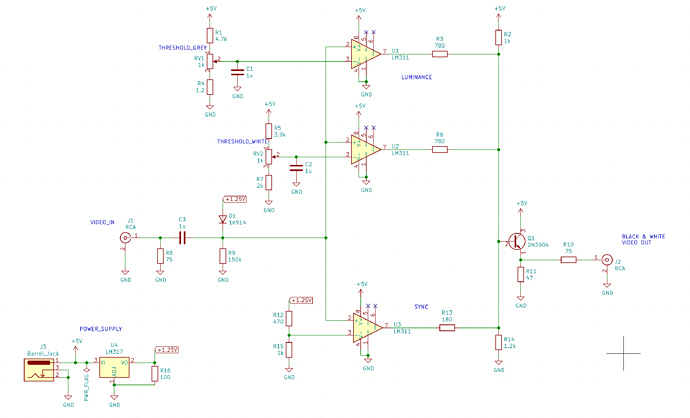
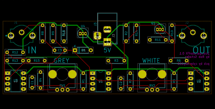
for this one i tried adding a third comparator to give a grey stage also (as Rob suggested), not sure if i got the resistor values quite right though will have to experiment a little i think. (heres the simulation where i was playing around with this )

schematic


pcb

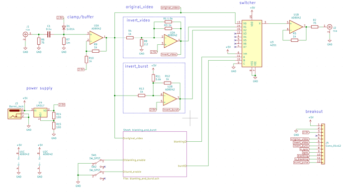
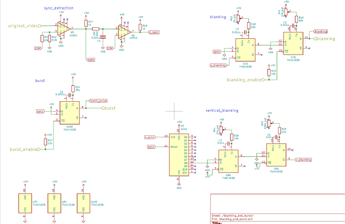
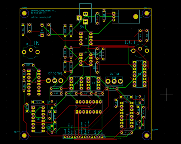
chroma-luma-invert

schematic


pcb

thanks @BastienL for some advice (as usual) ; happy to hear any thoughts , suggestions, mistakes , improvements etc

5 Likes

HOLY COW!! That’s remarkable. I’m completely blown away. I had no idea you were doing that.

Thank you.

1 Like

no problem - its a good way to help the learning sink in !

im wondering where you sourced AD8042 in dip ? i usually get these things through mouser , but they dont have it in dip , and it looks like even on the analog devices website you cant get dip samples from them

UPDATE: just seen that mouser has AD8044 in dip , so i could replace the design with one of these - but you have to buy minimum of 75 ! hmm lets see :thinking: ; digikey has the quad version available in smaller quantities

in the past i have used AD8072 in dip for some video stuff (its not rail-to-rail though) , do you think this could work in the invert-circuit ? i guess this is the flipside of having a single power-supply

1 Like

I bought all 75 of them!! (My severance ends in September so I’m stocking up.) I’d have been happier buying 20. Don’t know if you’ve watched my last lesson. (My later classes doesn’t have quite the “attendance” the earlier ones did.) But all kind of possibilities open up with a +/-5 volt supply. Anything that runs inside of only 5 volts had better be rail to rail. Please let me thank you again for laying out my circuits.

1 Like

And yes. You could absolutely use the AD8044. I don’t know the other opamp you mentioned. I used to use LT1253’s at +/-5 volts. They’re not as well behaved on the breadboard.

I’m looking at the spec sheet for the AD8072. It looks happy at 5 volts. Hmm. Works within 1.3 volts of the rails. Well, heck. 2.4 volts range will fit 2 times video. (I’ve gotten spoiled having rail to rail. I use the AD8042 for lots of things.)

From having a brief scan of the circuits @cyberboy666. I would highly recommend on the luma invert schema to have your trace further away from the mechanical aspect of your board. Bottom left is a bit too close to your drill hole.I’d also suggest to make your power traces wider to be on the safe side. It can end in tears from experience. I will have a look over your work during the week.

Got my final presentation for my RF/EE studies tomorrow and then its DIY city!

AD8044 at Mouser comes up as an unstocked item for me, and I can’t see AD8042 in DIP at all? And LM6172 DIP are cheaper than AD8042 SOIC. Unfortunately there’s no LM6174 in DIP :frowning:
I bought 75 x LT1251 a little while ago to get volume discount so @schaferob I feel your pain!!! :slight_smile:

Nice work @cyberboy666 and of course @schaferob :slight_smile:

About 2 comparators effect (or is it 3 comparators now? :thinking:) you can add 100nF decoupling caps for each IC supply pin, might work fine without it, but it’s always good to have them.

First the video signal is AC coupled using the 1uF cap, and then the 1N914 and 150k pulls the signal up to 600mV, so whatever signal at the input (AC or DC coupled), the signal at the input of the comparators will evolve between 0.6V and 1.6V.

Then the comparator used for sync has a threshold voltage of about 850mV, so the output of the comparator will switch between low and high according to sync (sync extractor).

The other comparator threshold is used for the luminance of the video, like, everything brighter than threshold will be white, everything darker will be black (or the other way around).
The potentiometer divider provide a voltage ranging from about 900mV (just a little above sync) to 2.2V, which is a little bit above the max voltage of the video signal, 1.6V, but it might be because the first version of the circuit didn’t had the clamp part and so it was dependent of the DC content of video signal (?).

I’ve edited the simulation with just the two comparators, also changed the threshold resistor, so the potentiometer can be used at full range.

Then, to add another comparator stage, first it requires to split the previous threshold range to the two comparators (previous was 0.9V->1.6V, so the lower comparator can be 0.9->1.25V and the high one 1.25V->1.6V).

Here is a small excel sheet to calculate potentiometer divider based on supply voltage, min/max voltage needed and potentiometer value https://docs.google.com/spreadsheets/d/1AwFTcx-UxtUp4F8azxw0s4nCCLAMrOF2gW4dwOxHHsI/edit#gid=0

Then the other thing that needs to be modified is the summing resistors at the comparators outputs.

Here is the simulation with the 3 comparators. I’ve modified the 1.2K resistor at the output with 1.5k, so it gives around 1V signal at the output, and then adjusted the summing resistor so it gives a sync at around 300mV, first comparator around 600mV, and last one at 1V. Also, this is basic simulation in circuitjs so, might need some value tweaking IRL.

Now, LM311 comes in a DIP8 package with only one comparator inside, so it could be swapped for either LM393 (which is also DIP8 but dual) or LM339 (DIP14 quad) if you want to save some space on the board, so you would have a fourth comparator, or another shade of gray :wink:

2 Likes

All good.I REALLY appreciate your wise comments and review.

Excellent. Thank you for helping!!

2 Likes

Certainly makes sense to use IC’s with multiple comparators. The LM311 has a cool output structure but it’s not at all needed for this application. Check out this quote from the spec sheet. “Their output is compatible with RTL, DTL and TTL as well as MOS circuits.” You gotta be pretty old to know what RTL and DTL are!!

3 Likes

thanks for the feedback everybody ! i have ordered already a first revision of both boards, will include these ideas on the next one.

@VisibleSignals yeah also couldnt find a good alternative for the opamp on mouser. have decided to source this one from digikey for now

@Zifor how thick would you run power traces ? the default in kicad is 0.25mm and i doubled this for power (0.5mm) here

@BastienL will experiment with these values when the boards arrive (can send u one too to play/help :wink: ) , and yeah good idea about using duo or quad comparator

2 Likes

The trace width for power should be At least 0.3, I suspect they are smaller, power trace should be as close to 1mm as possible.(So in this context if you can make the bigger , excellent!).
A few more suggestions

Please have a reverse voltage circuit to protect your hardware!

Include decoupling capacitors on the psu on each part. as example the power to U10 reaches it via U8,U5, U2 & U1. You should separate the wiring of the digital parts of the circuit from the analog section (U1,2&3), think of the board as being in 2 halves, the first U1,2&3 and then the digital section.

Also include the multiple paths from the regulator to the components, the issue is the way it is wired the last component on the line gets a dirty supply as th other components add their noise to the trace before it gets to that component.

The other big bit of advice i’d give is that a lot of your trace lengths are very long. You could easily reduce this by putting components closer to each other then negating noise , signal loss etc.

I hope this additional advice will serve handy for everyone designing circuits! Lets help eachother :slight_smile:

1 Like

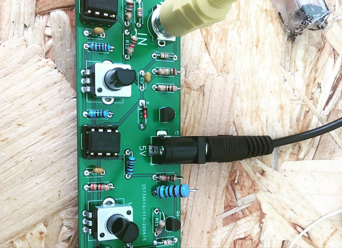
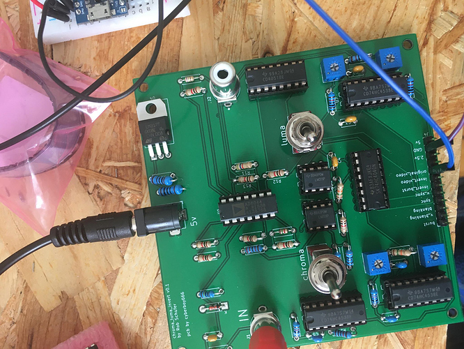
just a little update about these circuits. im currently building these from the first revision pcbs i ordered.

2comparatorFx

the 2comparatorFx circuit is working nicely - after some experimenting i landed on using the threshold resistors: +: 4.7k, g: 1.2k to give a voltage range of aprox: 0.88v - 1.6v on both pots.

this gives a nice range of 2 shade effects plus some glitchy / chroma bleeding at the extremes (which i like, but ofcourse could be removed with a different choice of resistors here)

i posted some examples of using this with the chroma bleeding effect:

btw i am mainly using pal sources although tested it with (what i think was) ntsc too and working fine / same on both

chroma-luma invert

this one is not working for me just yet. besides finding a bunch of little mistakes in my version of the schematic which required trace cutting / rewiring , i also have to hack some parts because i didnt have the correct value trimpots. also i am guessing that maybe some things (like line counting) may not be exaxtly the same if im using pal sources.

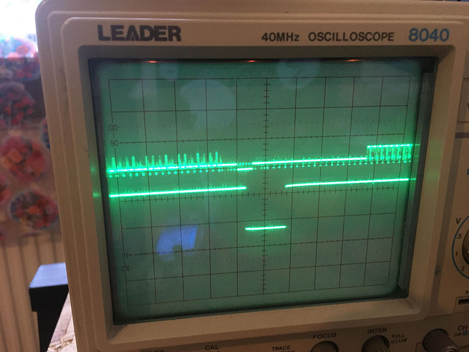
i realise i need a better scope for this because my one struggles to ‘lock’ onto the parts like vsync / blanking (or even show video at the line level very well) so very hard to debug further at this point

still everything seems to be working now except the blanking, which i am still a bit confused about.

this is the closest i have got to vblanking so far. using Q8 from counter output - although seems to 'overshoot the start of the blanking period… '. (Q9 like in @schaferob schematic didnt give any pulse , Q7 might be more promising but need to now adjust the one-shots )

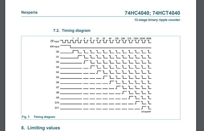
@schaferob in your video-lesson you say the that 4040 wants a positive pulse for reset, but the vsync pulse is a negative pulse no (usually high) ? or the reset is only looking for a rising edge and which is triggered at the end of the vsync pulse ? i didnt really understand this part in the datasheet (or this diagram really :sweat_smile: )

@schaferob one more thing: i think the sync threshold values in your schematic are swapped (10k / 3.9k on the first lm311 , atleast it worked for me after swapping these :slight_smile: )

thanks everyone else for the other feedback too, i think the second revision of these pcbs will be :fire: :fire:

2 Likes

I think I know what the problem is. You are absolutely right about the 4040 resetting with a positive pulse. And yes, vertical sync is traditionally negatively going. (Back in the day, WAY back in the day, all sync generator pulses were REALLY negative going. Zero to negative four volts. Into 75 ohms. So unterminated, the pulses went down to negative EIGHT volts!!!) I can see from your schematic the LM311 picking off the vertical sync is wired backwards. That is, pins 2 and 3 need to be reversed. (Then the reset pulse will be positive going.) Sorry I didn’t see that sooner.

Omg yes that’s it thanks @schaferob ! Actually I did notice this was wrong at some point , had already cut these traces on my board , but soldered them back in the same (wrong) spot lol

Will correct it and have another go tomorrow :smiley:

Caught some other silly mistakes on that schematic already , will post an updated version once it’s working !

1 Like

Excellent. It’s so cool you’re making these boards. (I know I already said that. But it’s REALLY cool.)

2 Likes

great to see progress on your boards :slight_smile:

1 Like

okayyy ! some progress :smile_cat:

so i got the invert circuit working ! (looks good on crt , a bit noisy on the lcd but thats maybe because i need some decoupling caps ? )

@schaferob two things i did differently to your schematic:

  • using the Q8 output from 4040 (actually this is what you say in the tutorial and it is pin12 on the ic - just a mislabel maybe ?)
  • the first oneshot input after the counter should be triggered from a low-to-high pulse. (i think when i had it the same as your schematic it was triggering on high-to-low , meaning vblank was starting at vsync , not before like in my picture above)

regarding ntsc/pal compatibility:

the 4040 on Q8 is counting 256 lines. since ntsc has 262 lines in a field, the oneshot only needs to fine tune over a couple of lines to fit. unfortunately pal has 312 lines in a field , so counting to 256 still leaves us a fair way off. the solution i am thinking of is just to measure aprox how long these ~56 lines are and increase the value of the resistor (R26 - currently 10k) to compensate. this way the same board can be built to do pal by just changing this value.

just wondering if this sounds good or maybe theres a better way ?

3 Likes