Notes from trying to build a recurBOY with a Eurorack PCB front panel:
Original project by @cyberboy666
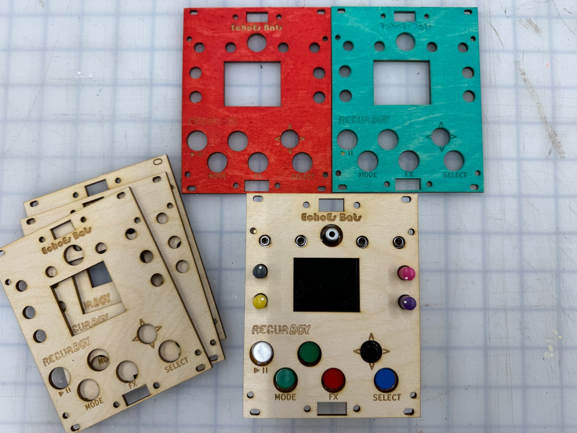
Front panel PCB by @BastienL
@BastienL’s current revision of the front panel PCB has an issue with the location of the CV jacks. They are spaced too closely together on the panel and don’t line up with the jacks on the PCB. They can be convinced to kinda line up if they are tilted slightly when soldering.
There doesn’t appear to be a path to ground for the ground side of the composite jack. I did a bodge wire from a ground pin on the Eurorack power connector to the sleeve of the RCA jack and composite video started working.
Having the Eurorack power socket on the front of the board makes the PCB front panel impossible to properly seat. The Eurorack power socket should be on the back of the board if using with a Eurorack-compatible front panel.
The orientation of the Eurorack power connector is overlooked in the build documentation. It should be oriented with the ‘key’ of the connector facing the SELECT button.
The screen just sorta floats freely on its ribbon cable. Not opportune for long term use. I added very small strips of double-sided tape on the extreme edges of the bottom of the display itself to keep it from flopping around. Don’t put any tape on the back of the display as it can interfere with the light pipe for the backlight.
It would be great if the display board was socketed so it could be removed and replaced without desoldering or if a repair needs to be made to areas of the PCB hidden by the display.
The RaspPi itself is mounted VERY high on the back of the unit. It would be better if this were mounted lower, closer to the center of the board. This just makes life easier with most Eurorack cases and allows the opportunity to easily jump the HDMI and/or USB to a front panel breakout using short breakout panel-mount cables. For desktop use, this isn’t an issue.
hii @bsom - thanks for all the notes ! its really helpful.
ah yes - you must have downloaded an untested version of the gerbers - this is a good reminder for me to start using the release notes and feature branches more on github for these revisions - i usually keep my WIP projects private until they are working so figure that no1 will be using em until bugs are fixed, but in this case i introduced this error while fixing another doh. anyway latest version of pcb is v0_7_1 and this is tested
agreed! most eurorack modules connect power on the back of the pcb
this is a good point ur not the first person to point this out to me - will def update the silkscreen for next batch and adding it to the documentation is good idea also - all docs are just text on github - feel free to add anything you thing would be useful - the more the better with these things i think !
im not sure exactly what you mean by this one ? the lastest version of pcb atleast has 4 mounting holes that you could connect to the four corners of the screen-board if you wanted to. although i usually dont bother - just connecting the header pins to the board and putting a small amount of foam between the screen and the pcb to give a little support works well enough…
yea this is a good idea - i have some recurboys with socketed screens exactly like this ! you could too - just means the screen is quite a bit higher from the pcb. but if u ok with this! i too have been caught out trying to make repairs under the screen. now i just have a desoldering pump so dont even bother with ic sockets most of the time tbh…
yeah i get what you mean - obvs the position of the pi on the board is made so you can access it from behind in desktop form. this is an example where having a different revision of pcb for eurorack version makes sense to me. also other design choices like position of the jacks etc would be different if designing for euro (also would go for smaller HP lol)
its my plan eventually to do eurorack revisions of all my projects (and for these use mainly smd parts for smaller form-factors / since euro-diyers usually are comfortable with this)
if you would like to help me with this / have any design suggestions im very open to it !
@cyberboy666
I’d love to be involved in the design/testing/etc. of a ‘proper’ Eurorack version of the recurBOY. I’m working on some of my own modules as well but I’m still currently in the component identification stage. I’ll be doing some prototyping/breadboarding soon.
My comment about the screen floating might be particular to the lot of screens I received. They are connected to their carrier board only by their ribbon cable. There is no other mechanical connection between the display panel itself and its blue PCB carrier board. I’ve had this happen with cheap Chinese displays before where they don’t do any kind of bonding to the PCB.
Your point about putting something between the board and the display carrier board does offer some extra stability as well.
As pointed out by @cyberboy666 in another thread, the Eurorack connector can be put on the back, as long as you make sure the key is facing the closest edge of the board. I’m an idiot.
doh ! ok that explains it lol. i pushed up the latest version im working with now so should be up to date.
iv been meaning to set up automatic jobs using github-actions to export gerber files from kicad and update release numbers and all that stuff to make keeping track of this stuff across multiple projects a bit more manageable … but everything in good time lol
Sharing my experience for anyone lurking like I was.
@bsom was able to sell me one of their extra PCBs and plates. big thanks!
I put a little super glue around the perimeter of the screen to keep from flapping around. Only slightly noticeable on start up (see photo) once one main select screen you can’t see it.
After tinkering with some options and frying my initial pi .
I came up with this option for anyone with a deeper case. Putting the pi at a 90degree angle. Also trimmed up one of those dual stick type joysticks and drilling into to fit the 5 way switch.
Still had to drill out the cv holes because of the horizontal spacing and the pot holes because the heavy duty style I used. But over-all it really does the job for now!
Apologies again for the wrong CV holes spacing, I’ll check to modify the gerbers based on the last Recurboy revision. Can also make the potentiometers holes bigger, as I used tall trimmers so the plastic shaft is smaller than metal shaft ones.
And cool to see you were able to use the front panel hole for the usb port, that’s what I had in mind, though there wasn’t enough clearance at the top of the RPi Zero to fit a cable because of the eurorack case rails getting in the way. Seems like mounting the RPi at a 90° angle was the solution, well done!
My first attempt to make a panel for the RecurBOY.
Some tweaks are needed:
I want to add a hole for a HDMI output.
I need to move the hole for the USB-port. The current position has three problems:
a) The adapter will prevent the panel to be racked, since it’s blocking the top rail.
b) The adapter will also be blocking the HDMI-port on the RPI.
c) There is not enough room to accomodate for the USB-micro → USB-adapter I have (maybe there are other slimmer versions that could fit).
The holes around the composite port, the screen and the joystick can be made a bit smaller.
The button holes need to be centered better.
Actually, I’m not sure there is enough room for the USB- and HDMI-ports on the panel. One solution could be to add those ports on an “expander” module. That expander could then maybe also host a port for the MicroSD-card. If the RPI was positioned more centrally on the PCB, then maybe all those extra ports could fit on one panel.
Yes, that’s an option. I’m thinking if I do it on a separate panel I’ll be able to leave that panel at home if I do a show where I’m pressed for HP in my live rack. It’s also a tad bit more flexible in that I can choose on which side the expander panel goes - it could even go on a row above or below the actual RecurBOY.
@elwood’s solution with a standing RPI is very neat, but runs the risk of making the module too deep for me.
I still need to find a USB-adapter that will fit under the rail. It woun’t help that I lower all the holes as far they can go before hitting the lower rail. It’s still too tall.
ahh damn yeah i was hoping that there would be room for the connectors at top of unit if the pcb was positioned as low as it can on the panel… but maybe not…
you can get very small usb-otg adapters if that would help:
great solution for racking recurboy for now ! one day i will design a eurorack specific pcb for it which wil take into account all these things people have been discovering
I also bought a joystick cap that works a little better than the original one. This one is in soft rubber which give a better grip. But it’s a bit shorter, so it doesn’t really reach through the panel. Ideally, I would want a similar cap that is a bit longer, or redesign the PCB so that the joystick buttom comes closer to the panel.
As mentioned earlier, I found a USB adaptor with an angled connector. This fits exactly on the top when I have lowered the PCB as far as possible. I would prefer some more wiggle room, but this still works.
I also made the expander panel for USB- and HDMI-ports. Both work, but my HDMI-adapter has a very long and inflexible cable so it’s a bit cumbersome to fit it into the case. I’ll probably not use this until I find a better HDMI-adapter.
I don’t have any Gerber-files to share since I used Schaeffer to make the panels, and they use their own proprietory application for designing panels. If anyone wants to try this, let me know and I’ll send you the files.
I tested out the Eurorack front panel with the untested mounting holes for USB and HDMI breakout cables.
Results:
There isn’t quite enough room to connect the breakout cables to the Raspberry Pi and mount them to the panel simultaneously, due to the original layout of the recurBOY.
The HDMI cable I used has a raised groove around the output side, so the mounting hole wasn’t large enough for it to sit flat.
Without calipers, I estimated the measurements using a ruler, including allowances for the wider HDMI breakout and spacing between the breakout cables and the recurBOY PCB.
I’d love to hear your feedback on these designs—especially if you spot potential issues or have suggestions for improvement!
Amazing! Hadn’t thought of placing the bracket below the Recurboy, I’ll have adjust the design. What kind of adapter did you use for the HDMI breakout to the Pi?