introduction
understanding video synchronisation pulses can be a barrier for people learning about video synthesis. they are both essential to displaying anything (correctly) and a bit mysterious - a good sync pulse is invisible to the user by design !
in a series of tutorials here i want to provide a practical introduction and exploration of how to generate your own video sync signals. we will be using the widely available and beginner friendly arduino family of micro-controllers.
this first tutorial will focus on VGA sync to introduce some key ideas and get familiar with the tools. some future topics may include:
- generating composite video sync
- ntsc vs pal
- progressive/‘fake’ vs interlaced
- how to lock to an external signal (a hack)
- how to lock to an external signal (for real)
- other non arduino approaches
chapter 1. generating VGA synchronisation pulses
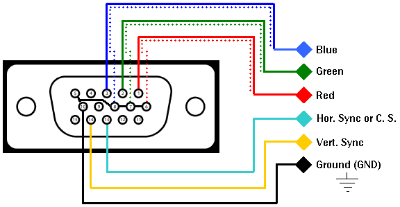
the way that VGA breaks out the Red, Green, Blue, Hsync & Vsync signals onto separate channels makes it a perfect place to start. maybe you have already hacked video on VGA following tutorials by cracked ray tube or jonas bers ? or you just wondered what went on inside those ‘black blob’ Chinese Signal-testers (and maybe how to replace it with an open source solution in your setup ? )
the tools
if you want to follow this tutorial at home i will list the things im using (feel free to try replace with what you have - leave a comment if you get stuck!)
- arduino nano (from my experience one of the cheapest and most commonly available in the family)
- a computer with arduino ide installed, and the usb cable to connect it with the nano
- an oscilloscope *
- breadboard, some jumpers, some cables between the scope and a breadboard
*for the oscilloscope (which many beginners may not have lying around): it is pretty hard to ‘see’ sync without one - you could always try following anyway and just hope it is working, otherwise there are usually old scopes quite cheap on the used market. sigrok is open source software that supports some cheap usb scopes or a local hackspace should have one you could use
some theory
- Hsync is a signal, usually high , that pulses low to mark the start of each line
- Vsync is a signal, usually high , that pulses low to mark the start of each frame
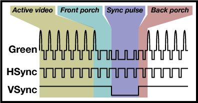
the frequency of these pulses determines the resolution of the resulting image. for this tutorial we will be generating a VGA signal at 640 x 480 @ 60Hz. the exact same method can be used to adapt this code to other resolutions (say for an hd vga synth for example !)
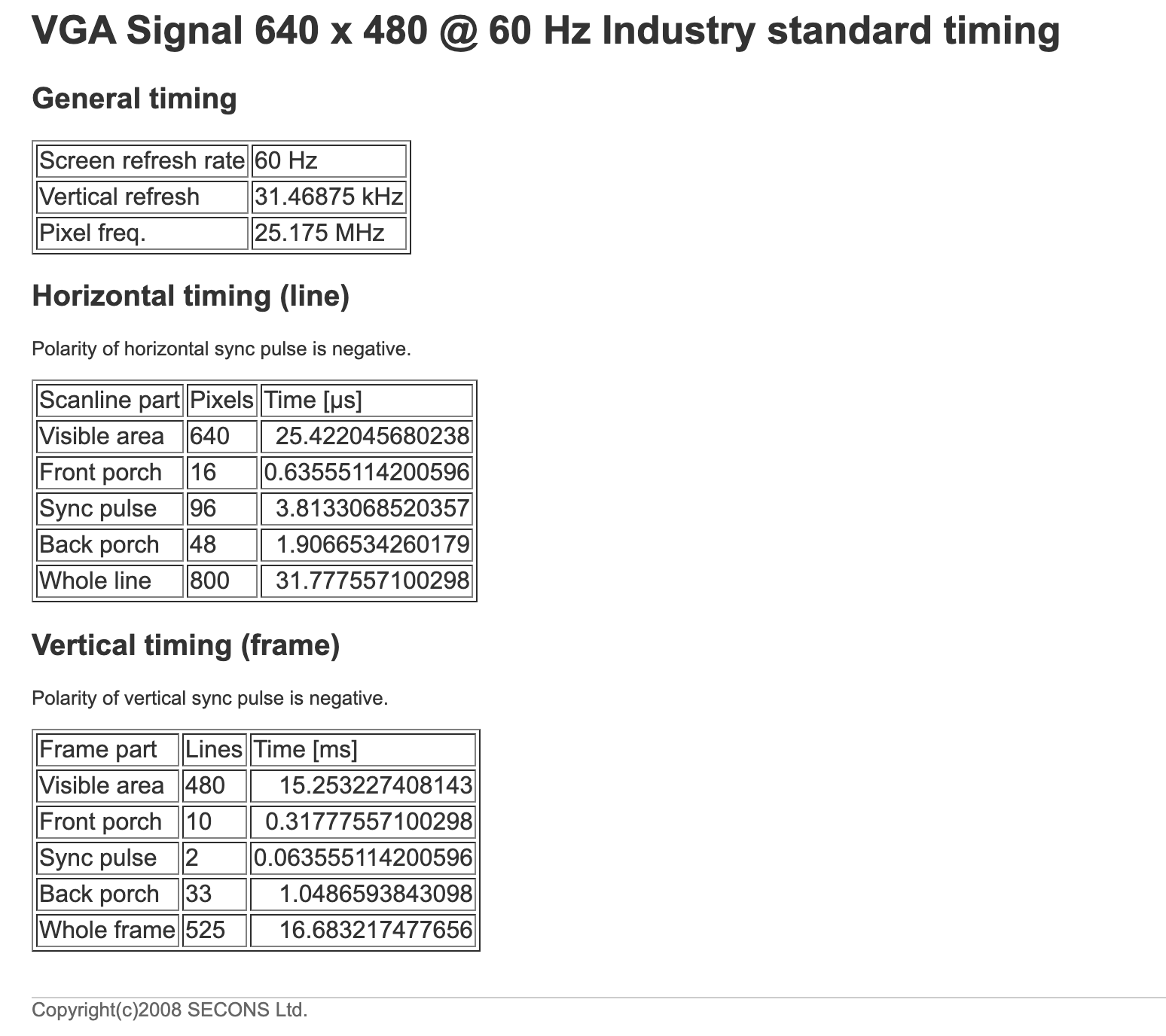
the timings for this VGA resolution can be found at tinyvga:
converting timings into clock cycles
an arduino measures time based on cycles of the crystal oscillator that clocks it. the nano has a 16Mhz crystal (small silver component close to the atmega ic), which means it counts 16 million cycles per second. (16 cycles per micro second) we want to convert the relevant horizontal sync timings into clock cycles of the arduino for use later:
- whole line : 31.78 micro seconds → 31.78 * 16 = 508 cycles (rounded down)
- h sync pulse : 3.81 micro seconds → 3.81 * 16 = 60 cycles (rounded down)
some other useful information to note down now:
- whole frame → 525 lines
- v sync pulse → 2 lines
hello blinky
lets quickly start by getting to blinky - the hello world of micro-controllers. if this part is too fast you can find many more tutorials to help:
- connect the nano to the computer
- install and open the arduino ide
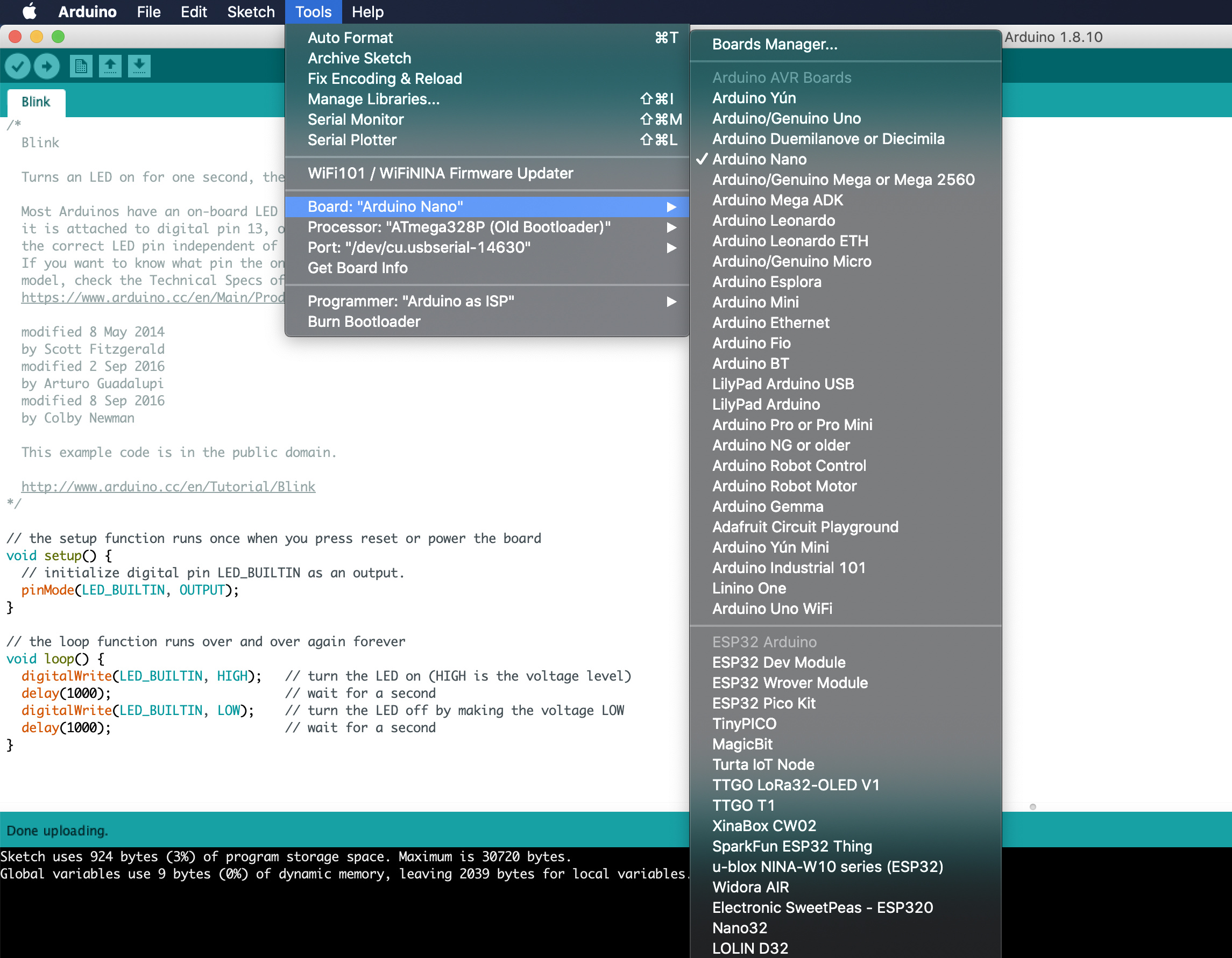
- go to tools → board → Arduino Nano
- go to tools → port → (usbserial) ← something like this
- (i had to also choose tools → processor → .. old bootloader)
- open files → examples → basic → blink
- press the verify tick → then if no problems the upload arrow
if all went well you should now have a blinky led. yay! now time to start writing the real sync code !
defining variables:
#define LINE_CYCLES 508
#define HSYNC_CYLCLES 60
#define VSYNC_LINES 2
#define FRAME_LINES 525

#define VSYNC_HIGH bitWrite(PORTD, 7, 1)
#define VSYNC_LOW bitWrite(PORTD, 7, 0)

volatile int linecount;
this is the initial code that sits before and outside of the setup() or loop() functions. we use the #define flag to tell the precompiler to replace all occurrences of the word LINE_CYCLES with the value 508 (and so on). this is used to make the code easier to understand.
we are also defining two new things here:
- first is the command
bitWrite(PORTD, 7, x)which means set pin D7 high/low - declaring a variable called linecount as a integer. this will be used to keep track of which line we are on inside the code
note: if you have used arduino before you might be more use to setting pins high/low with the digitalWrite() function - the bitWrite is slightly less user friendly, but faster, which is important for these strict timing applications
introducing timers
most arduino applications use a procedural programming style. this means you give a list of commands to execute and it will step through executing these one by one, usually in a loop , forever. for example you might say:
- read the value of this analog pin
- scale and convert this value to a midi note
- send this note over serial
- back to read analog pin ..
this approach is fine when the exact timings is not essential, but doesnt work so well for applications like this where we need to set a pin low for exactly 60 cycles. this is where timers come in. we can configure them to do things exactly like this. a timer is configured by setting values in its registers- which you need to look up in the datasheet.
hsync on timer1
  //inverted fast pwm mode on timer 1
  TCCR1A = _BV(COM1A1) | _BV(COM1A0) | _BV(WGM11);
  TCCR1B = _BV(WGM13) | _BV(WGM12) | _BV(CS10);
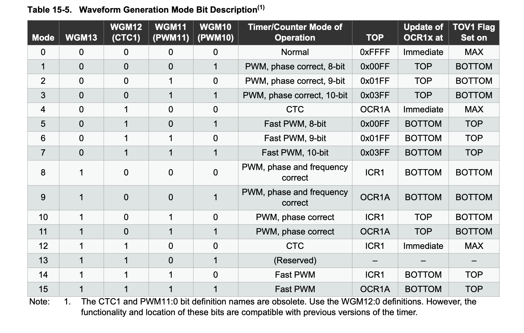
these cryptic looking lines configuration timer1 to inverted fast pwm mode. a good tip for finding out what these values mean is to search for them in the data sheet. TCCR1A stands for Timer Counter Control Register 1A. _BV() is used to set a bit value within the register high. in this case we can see that for the WGM1 bits (Waveform Generation Mode): WGM11, WGM12 and WGM13 are high. the table in the datasheet shows this corresponds to mode 14 - fast PWM:
setting high bits COM1A1, COM1A0 selects inverting mode:

finally the bit CS10 is used to enable the timer with no scaler. what this configuration does:
- the timer will reset (overflow) when it reaches the TOP - value set in ICR1 register
- the compare pin OC1A will be set high when the timer reaches value in OCR1A , and low again on overflow
to achieve VGA hsync all we need to do is set the timer to reset at end of each line (508 cycles), and set the compare pin to high after 60 cycles (length of sync pulse)
 ICR1 = LINE_CYCLES; // Overflow at Cycles per line
 OCR1A = HSYNC_CYLCLES; // Compare high after HSync cycles
test 1: just hsync
lets combine what we have seen so far into a actual sketch for the arduino:
#define LINE_CYCLES 508
#define HSYNC_CYLCLES 60
#define VSYNC_LINES 2
#define FRAME_LINES 525

#define VSYNC_HIGH bitWrite(PORTD, 7, 1)
#define VSYNC_LOW bitWrite(PORTD, 7, 0)

volatile int linecount;

void setup(){
  pinMode(7, OUTPUT); // VSync
  pinMode(9, OUTPUT); // HSync
  //inverted fast pwm mode on timer 1
  TCCR1A = _BV(COM1A1) | _BV(COM1A0) | _BV(WGM11);
  TCCR1B = _BV(WGM13) | _BV(WGM12) | _BV(CS10);

  ICR1 = LINE_CYCLES; // Overflow at Cycles per line
  OCR1A = HSYNC_CYLCLES; // Compare high after HSync cycles
}

void loop(){}
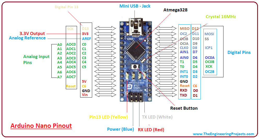
you can see we have put the timer1 config code inside the setup block and added setting pins 7 and 9 as outputs. we need to also include an empty loop function even though it will not be used. (some of the values we defined earlier are not used yet either). try pasting this code into your arduino ide and uploading it. if it uploaded successfully it is time to check on the scope. to find which pin on the nano is OC1A a diagram like this can be useful:
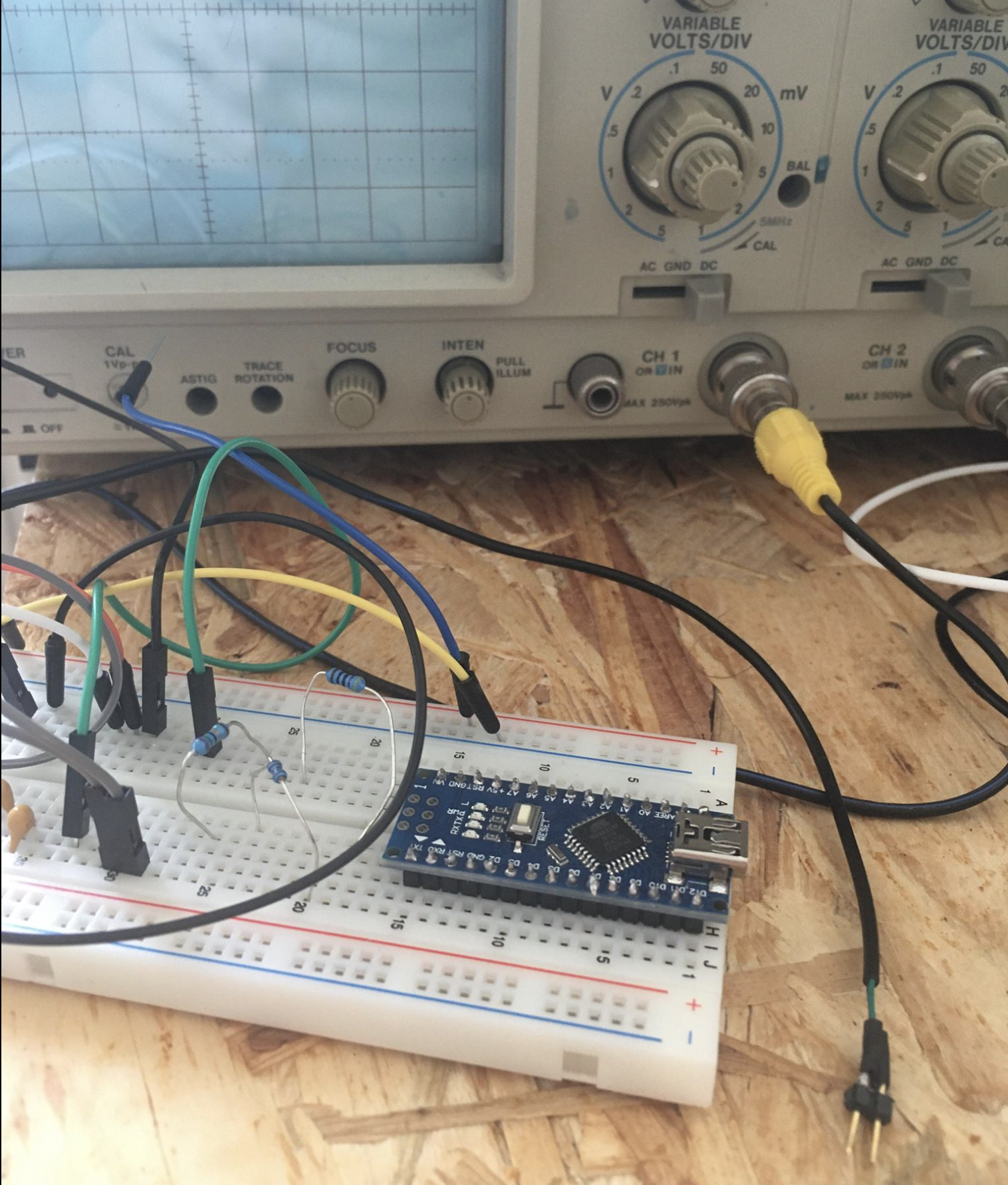
connect both ground and the pin D9 to a channel on the oscilloscope:
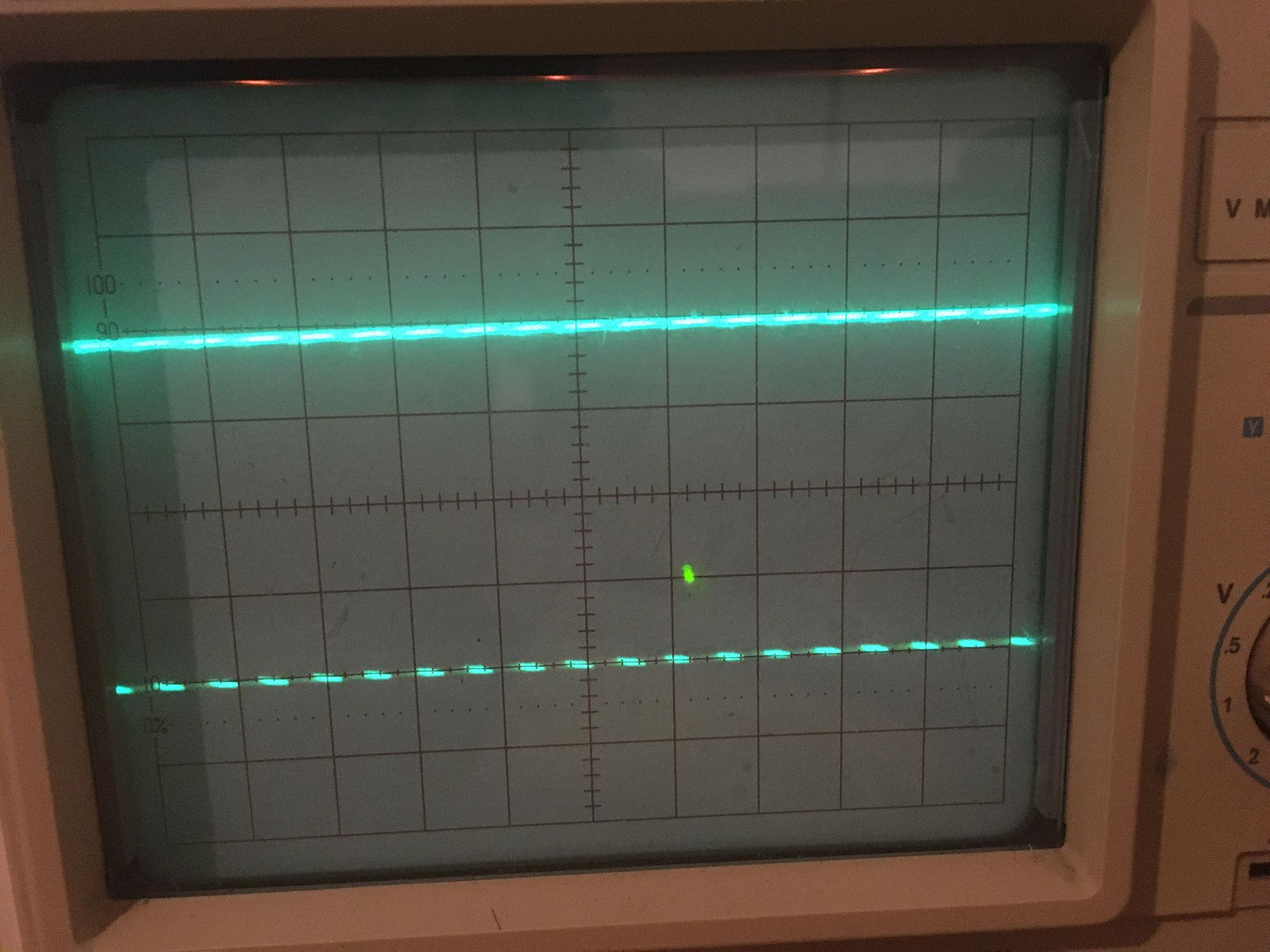
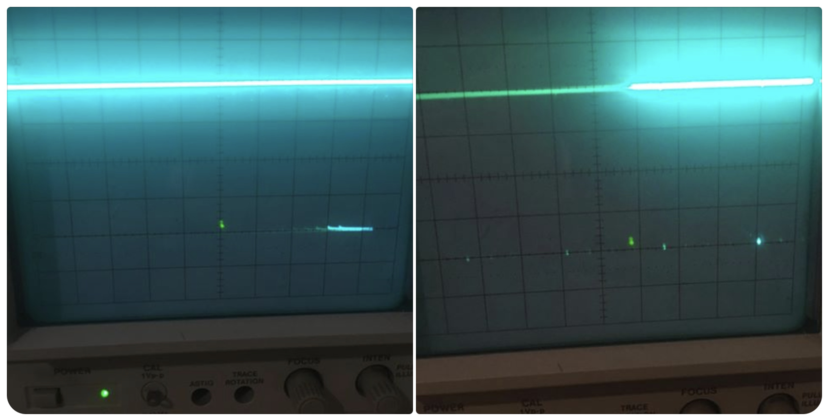
here my scope y axis is set to ~20 micro seconds per square → which looks about right for scanlines of ~31uS (it is hard to photograph well because of my old scope and the scrolling but) can see that the signal is mostly high with some regular dips low at aprox the frequency we expect
introducing interupts
we needed to use the comparator on our timer1 to set the hsync pulse, however we will be using a different method for vsync. the hsync pulse is close to the clock frequency (only 60 cycles wide) whereas vsync is much slower. a full frame is 16ms which amounts to 16 * 1000 * 16 = 256000 cycles. rather than counting cycles for the vsync we would rather count lines. (this is why we defined a variable called linecount eariler)
for every line we want to increment the line count and check if the vsync pulse should be set. to achieve this we will use a Interrupt Service Routine (ISR). these are functions which rather than being called in a procedural way are triggered by some event and interrupt whatever the processor was doing to run them. here is a useful resource for learning more.
vsync on pin d7
in our case we want the trigger to be whenever timer1 overflows ( as this marks the start of a new line)
void settings(){
...
TIMSK1 = _BV(TOIE1); // Enable timer overflow interrupt
...
}

ISR(TIMER1_OVF_vect)
{
...
}
first the interrupt on timer1 overflow needs to be configured, and then the function that this trigger will call can be defined: Interrupt Service Routine (ISR) on Timer1 Overflow Vector (TIMER1_OVF_vect)
now we can write the logic that (as stated above) sets the vsync pin low for 2 lines, and resets the line count at 525:
ISR(TIMER1_OVF_vect)
{
 if (linecount == 0) VSYNC_LOW;
 else if (linecount == 2) VSYNC_HIGH;
 else if (++linecount == FRAME_LINES) linecount = 0;
}
test 2: hsync and vsync
putting it all together now - try uploading this to the arduino and looking at the scope on pin d7:
#define LINE_CYCLES 508
#define HSYNC_CYLCLES 60
#define VSYNC_LINES 2
#define FRAME_LINES 525

#define VSYNC_HIGH bitWrite(PORTD, 7, 1)
#define VSYNC_LOW bitWrite(PORTD, 7, 0)

volatile int linecount;

void setup(){
  pinMode(7, OUTPUT); // VSync
  pinMode(9, OUTPUT); // HSync
  //inverted fast pwm mode on timer 1
  TCCR1A = _BV(COM1A1) | _BV(COM1A0) | _BV(WGM11);
  TCCR1B = _BV(WGM13) | _BV(WGM12) | _BV(CS10);

  ICR1 = LINE_CYCLES; // Overflow at Cycles per line
  OCR1A = HSYNC_CYLCLES; // Compare high after HSync cycles

  TIMSK1 = _BV(TOIE1); // Enable timer overflow interrupt
}

ISR(TIMER1_OVF_vect)
{
 if (linecount == 0) VSYNC_LOW;
 else if (linecount == 2) VSYNC_HIGH;
 else if (++linecount == FRAME_LINES) linecount = 0;
}

void loop(){}
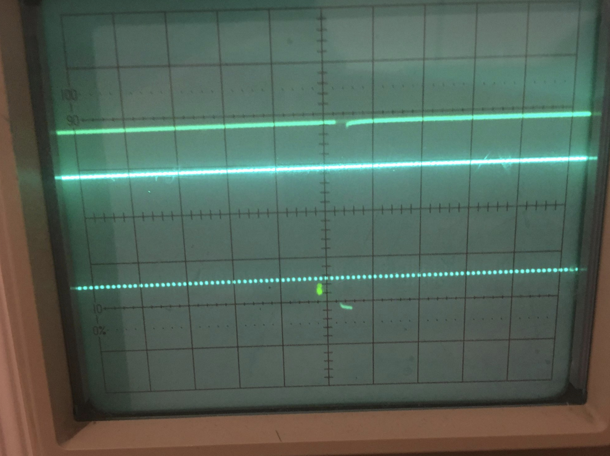
here are my attempts to capture the vsync - the first is ~50us squares, where the low pulse should be ~60us (so just over one square long), the second is at a much slower rate (10ms , where low pulses should be 16ms apart so ~3 sqaures) but hard to see because i would need to increase the exposure on the camera.
if you have a 2 channel scope you can even try looking at both pulses at once:
note on voltage levels: the vga sync pulses should be tll - which expects low when between 0 V and 0.8 V with respect to the ground terminal, and high when between 2 V and VCC (5 V), which is the same as arduino nano digital pinouts.
congrats ! you have now generated your own vga sync pulses ! and all in under 30 lines of code ![]()
