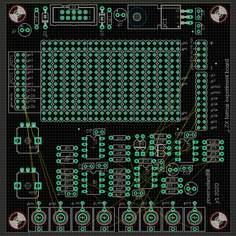
I was laying out a PCB for some video experiments.
While doing this I thought it might be interesting for others, too.
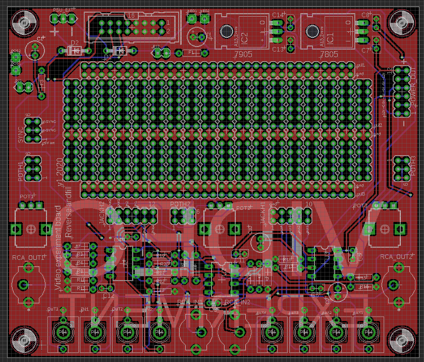
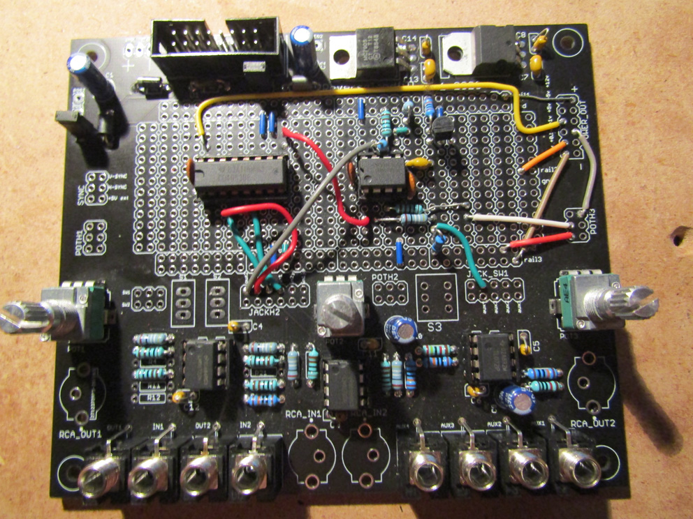
I am not a big fan of solderless breadboards, so this pcb is aimed to use the layout of the breadboard while soldering the parts.
The idea is that you an solder a prototype and connect it easily to the headers with wires or jumpercables, while the common building blocks are pre-made. (see below)
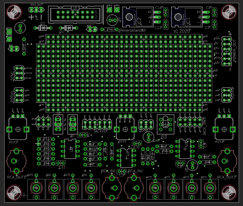
The voltage sources are placed near the rails of the ‘breadboard’ , so you can connect +12v or +5v to them. The GND rails are pre-connected.
Note that the values of most components are not yet correct and the features are not yet set in stone. Early stage design!
I want to be able to do CMOS / lunetta style video experiments, LZX type format, and possible standalone composite video stuff.
Most features are based on the Cadet and Castle schematics.
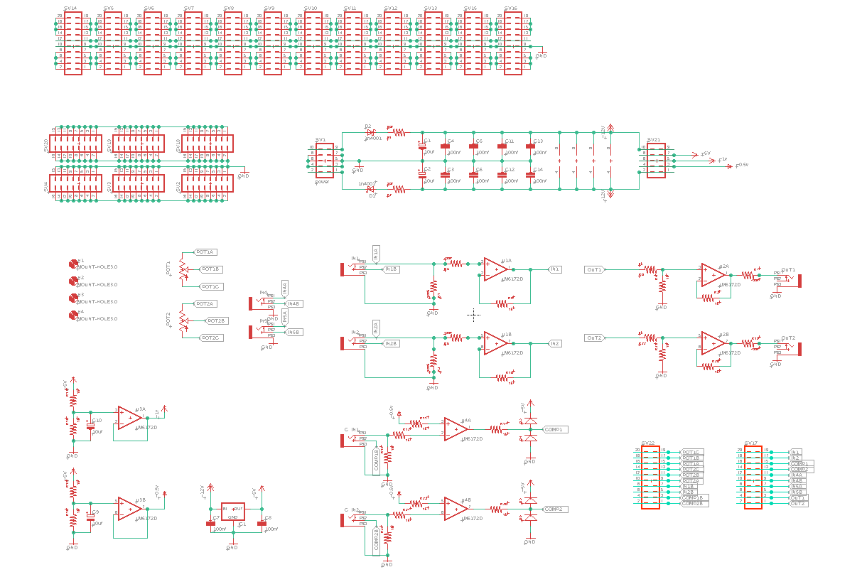
Current features:
2x input buffer
2x output buffer
2x comparator
2x jack aux
2x potmeters
2x Pinheaders for all function connections. (I’ll add a legenda somewhere)
The power pinheader has : +12v, +5v, +1v, +0.5v, -12v
Header access to the jacks and jack switches
I want to make the opamp configurations in such way that they can be multi functional, let’s say as buffers, comparators of amplifiers. I still have to find a good method for this.
But this will make the board more open-ended.
I might add composite video, @BastienL has given me some tips about this already.
The aim is to make several versions of the boards:
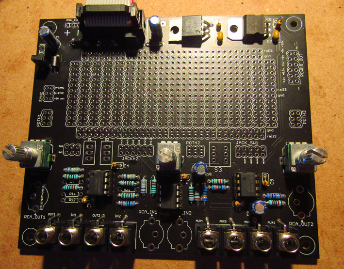
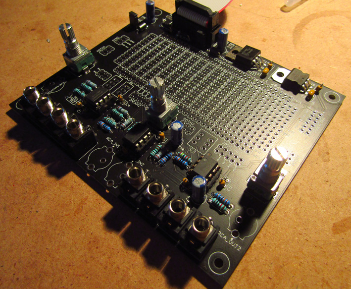
a medium sized board (like the picture above)
a big board - more protospace and features
an eurorack pcb&panel for more permanent prototypes
If any of you have tips / hints / feature requests, please tell me!
I want to make this board as useful as possible, for everybody!
The project is also posted here, as a discussion.