encouraged by the success (and fun) of building these circuits from @schaferob whiteboard-schoolhouse (just realised iv been calling it your whiteboard fun house this whole time lol) was thinking would like to give this colorizer a go too. since this will likely lead to some more questions lets start a new thread !
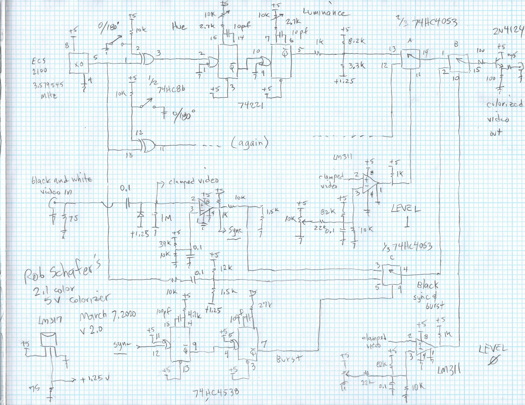
some details (pulled from this fb post )
- runs on (single) 5v power
- for black & white ntsc video
- 2 full colours plus black
discussion around adapting for pal
there is more on this in the fb comments, but in summary (@BastienL writes ) :
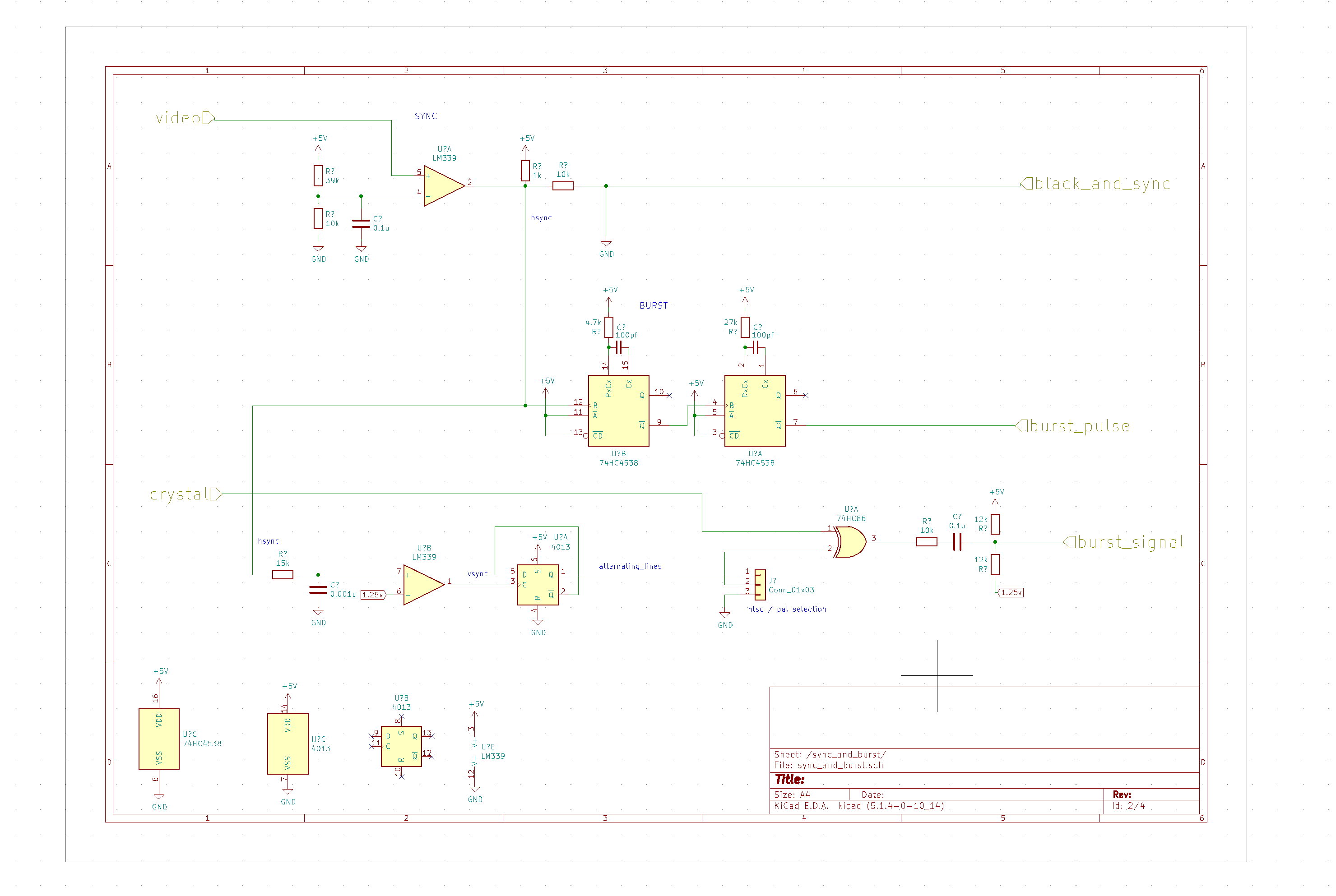
actually I don’t think it makes it particularly more complex. I guess you only need to replace the quartz oscillator by a proper frequency quartz, and then as Rob said, a flip flop can take care of dividing the horizontal sync signal by 2, with 50% duty cycle, which means the output signal will remain high during a line, then will go low during the next one, and so on. The 180° shift is already implemented in the circuit, so using the signal generated before, you should be able to drive the two XOR. Then instead of taking the signal for the burst reference directly from the oscillator, you should take it at the output of one of the XOR, so it also get inverted every other line.
5 Likes
some questions i have already  (hope its not too much)
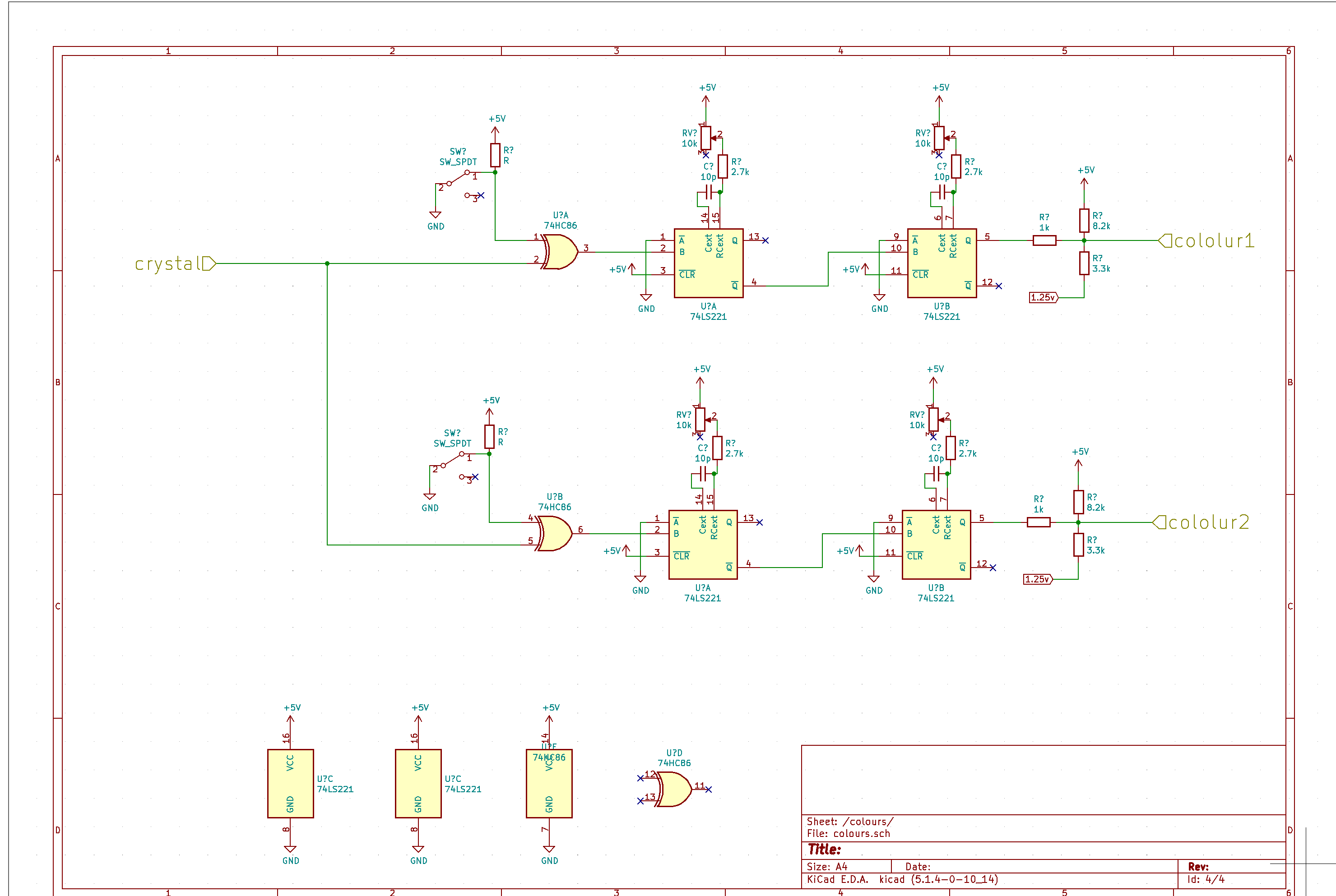
- what is the difference between using TLL oneshots and CMOS oneshots ?
- how is it that the 74221 oneshots control the hue and luminance of the sub-carrier ?
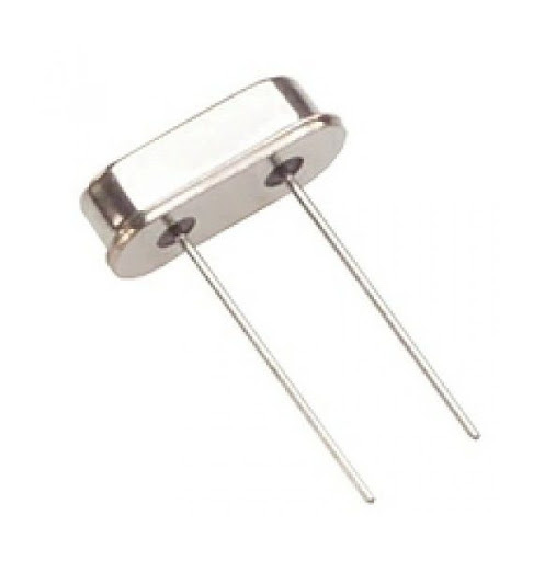
- is there a difference between the crystal you use here and the ones that look like this ?
- what is the difference between quartz oscillator and “proper frequency quartz” (maybe this is the same question?) and why would it be better for inverting chroma / pal ?
and finally, what do you think about using LM1881 in a design like this ? i really enjoyed doing the sync extraction ‘by hand’ in the chroma-luma circuit. its not that much more components, prob saves a bit of $$ vs less parts, less time… what other factors are there ?
The one on the picture with 2 pins is a crystal resonator, which means it is passive, and usually requires to be in the loop of an inverter to oscillate, with 2 capacitors to ground. Micros like Atmega usually have their own inverter inside (the 2 pins that are connected to the crystal).
The one used by @schaferob is a crystal oscillator, which integrates the inverter and capacitors, so it usually has 4 pins (Power, Ground, Output, Enable), which is useful when you don’t want to use a whole chip for one inverter or if the integrated circuit it will be tied to doesn’t have its own inverter.
I said “proper frequency” but I meant “proper frequency for PAL” 
So changing the 3.57MHz crystal (NTSC) by a 4.43MHz crystal (PAL). Then, the chroma inversion is independent of the crystal frequency, it is required for PAL (Phase Alternating Line) but not for NTSC.
To detail what I said about PAL adaptation of the circuit:
-
first, change for a 4.43MHz crystal to have the right subcarrier freq for PAL
-
then you’ll need to add a D flip-flop (74HC74 for exemple): Sync is sent to the clock input, /Q output is tied to D input, Q outputs the sync divided by 2
-
remove the switches and resistors tied to 74HC86 pin 2 and pin 12, and connect it to the Q output of the flip flop.
-
disconnect the 10k that is tied to 74HC86 pin 13 and connect it to pin 11 instead.
Then, I’m not sure what would be the best way to implement both NTSC and PAL, would require some switching for subcarrier frequency and phase alternation.
2 Likes
CMOS one-shots are way too slow. Using the terms “Luminance” and “Hue” is stretching it quite a bit. For one thing, changing the luminance will also change the hue. More accurately would be “phase shift” and “duty-cycle.” It’s a squirrelly way to make colors. With two knobs and a switch you can reach a LOT of colors. But you have to find them. One thing completely missing: grey! And no subtle colors either.
It’s similar to the way the Apple II got its low-res colors.
3 Likes
thanks a lot @schaferob @BastienL ! it is all coming together now 
i will try with both anyway, but then do you see any problem in swapping the TLL monostables for something else also with a small Propagation Delay Time ?
based on my mouser search would something like SN74AHC123AN be suitable ? (i would be much happier using a couple of 40c ics over some $5 ones if possible )

thats awesome !
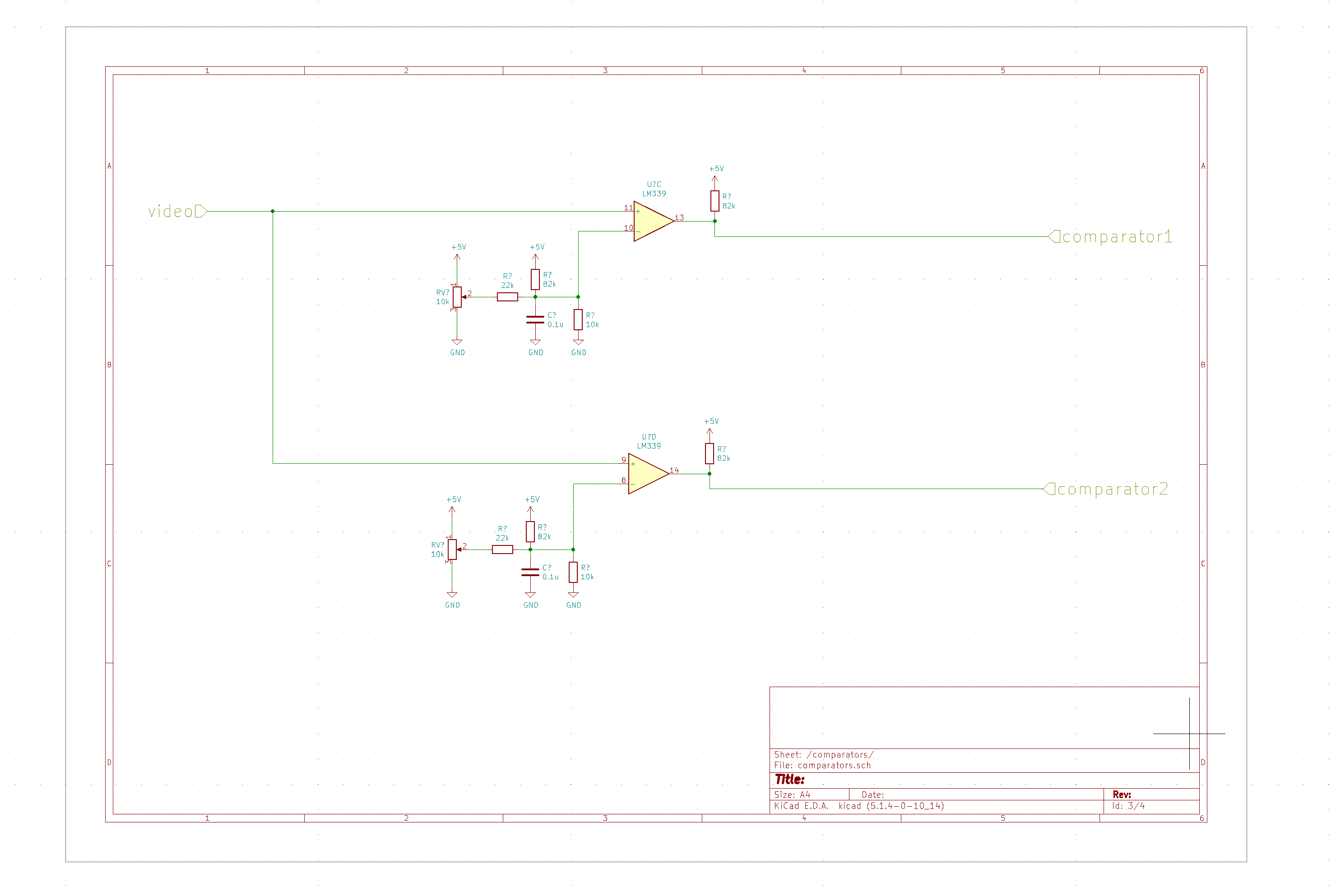
just thinking aloud, but, the amplitude of the subcarrier corresponds to saturation no ? so would that mean varying the resistance somewhere (after the 74221 stage maybe?) would be possible to tweek this ?
Sorry about the cost of the 74221’s. But there’s no way in hell the HC family can function in this application. We need at least 140nS of variation to get around to all the colors. And it needs to recover in time to make another pulse. The narrowest pulse has to be less than 70nS. The second one-shot has to trigger on the falling edge of a 50nS pulse!! Trust me, there’s no point in trying.
Your idea about a pot reducing the gain/saturation is a good one. (I forget your pots live down on the circuit board.) You could control luminance in the same manner. ALL the colors could be reached this way. But…
Here’s the deal. I don’t love this circuit. Mixing digital (particularly old TTL) with analog is nasty. I didn’t include it in my “fun house” 'cuz it’s not any fun for me. It works, but it’s cruddy.
The fact that Denise Gallant’s Synopsis effort combined TTL with analog cleanly (achieving 720 degrees of smooth phase-shift) still amazes me. One reason we got away with it is the comparators we used had separate power supplies. The 5 volts gets REAL noisy with TTL yanking up on down on it. Of course we never had ground planes.
How hard is it for y’all to get to component video? I purchased a composite to component converter and the opposite, hoping they were inexpensive enough to open the door to a MUCH more wonderful world. The pair was over $100 so… maybe not.
There are other reasons I don’t love using one-shots to make phase shift. One is the problem of yellow. (LOTS of baby-shit brown before you get up to yellow.)
I know I’m crazy about wanting clean circuitry and signals. It’s alien to the bending and glitching culture. (Sometimes I feel like I don’t belong because I tend to ignore issues of cost.)
Have I rambled on enough?
4 Likes
I’d be happy to give you that breadboard with all it’s components. It’s an old chassis not in the format I exclusively use now. (There’s my damn exclusivity again!!)
What’s your address? (If you want it.)
i think its super important, even for glitch designers to have a decent grasp if how to get the clean signal sides of things covered. its way easier to break the rules when u know what they even are to begin with
5 Likes
thanks again for the insights @schaferob !
and the cost is no problem for me. if it is necessary - i just know its not something you are thinking about much with these designs (and rightly so ! ) so maybe you used this ic because it was in the back of your draw already , and not because you researched every averrable option with cost-optimization in mind lol
i believe you that it wont be possible with with HC family. but i do want to get better at reading datasheets and inferring the limits of certain parts in certain applications in general (if you will bear with me lol)
it often takes me a long time make sense of these things, but from what im seeing here it sounds not too far off the timings you mention ?
pulse duration going down to 5ns and retrigger time typically at 60ns … what am i missing here ?
hehe i respect that. but yahh hacky things have always been fun for me - hope you dont mind me dragging it through the mud lol
it takes all sorts ! you need the purists to design things right, and also those excited to cut corners…
i see the cost thing as just another challenge, and also an opportunity to evangelize (at my work they call this the funnel lol) , more people might be willing to join a workshop (building even a simple/hacky circuit) with $5 worth of parts than $50. from those a few might be excited enough to take it to the next level (and so on)
speaking of , yess - looking forward to working my way up to component video soon !
thats very generous of you ! and ofcourse i would love it - can send my address in a pm - but i live berlin, not sure how the international postage is the other way but im still struggling to send some circuits to the US since march (you can as a business or just recently for like 55€ as a private customer ) so yah happy to wait for smoother times , maybe i visit NY again one day soon and we exchange some circuits in person 
I can see from the data sheets why you think it’s not impossible to use HC series instead of TTL. I’m speaking from experience that HC is slower than TTL. But… I can ALWAYS be wrong!! The TTL in this design is being pushed to its limits. BUT… the breadboard has something like 3pF from row to row.
How cool it is you live in Berlin!! I keep forgetting how crazy the cost is to ship stuff across the Atlantic Ocean. Guess we 'mericans move zillions of tons of stuff in trucks and trains.
In the pre-Covid days I’d have just eaten the cost 'cuz it’s so cool all the work you’ve done. Since my wife got furloughed and my severance runs out soon I’VE got to start caring about cost. (I am SO spoiled that way!!)
If you’re okay paying the shipping I’d HAPPILY send you the circuit.
I want to believe there’s a future where the world will return to something approaching pre-covid. (C’mon vaccine, c’mon vaccine…!!) THEN we can meet in New York. I’d love to show you my lab.
2 Likes
@schaferob sounds great thank you a lot - i will check shipping costs and get back to you at some point - lets see how things how things pan out re x-atlantic travel !
very looking forward to it !
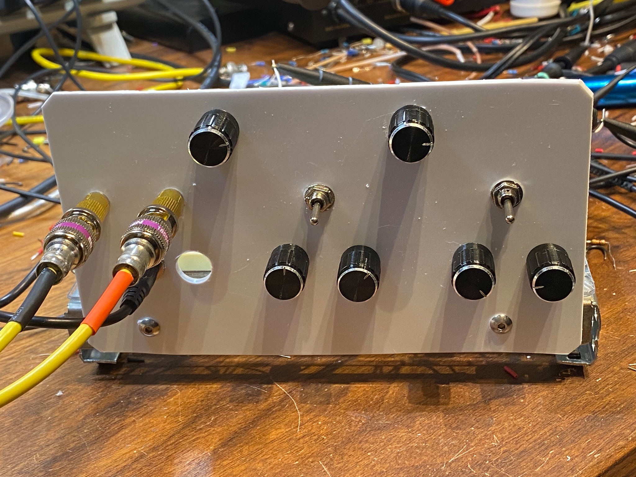
meanwhile here is a first go at creating this circuit. still got to do routing, but should have something to order by my next pcb run:
4 Likes
After making the pompous statement that the 74HC4538 can’t possibly go nearly fast enough (this from experience, not the spec sheets) to replace the 74221 in this circuit I figured I’d better take another look at it. I’m using a 74HC4538 in my current ramp generator attempt so I checked to see the fastest pulse it’ll make.
. That’s a 1k resistor and no cap. A 10k performs exactly the same so the 3pF on the breadboard isn’t a factor. 260nS. To be of use in the 2.1 color colorizer the shortest pulse should be like 20nS.
About what I expected. I HATE TTL. It’s very noisy. I only used it cuz I had to for the circuit.
Thanks for reading all my blah-blah. Again I want to tell you how much I appreciate the work you’ve done on laying out my circuits!!
5 Likes
Oh wow hehe that’s way too slow ! Well thanks for checking anyway , ooh this reminds me maybe it is time to upgrade my scope !
1 Like
This looks really interesting! Will the PCB files be available to download, or can we buy a copy whenever it’s finished? Keep making art <3
1 Like
hii @hugdealer -> yahh everything from this lil project will be open source so the files will be available + maybe will have some to sell/share at some point. actually just received the first version pcb today so will test it when the components arrive and report back 
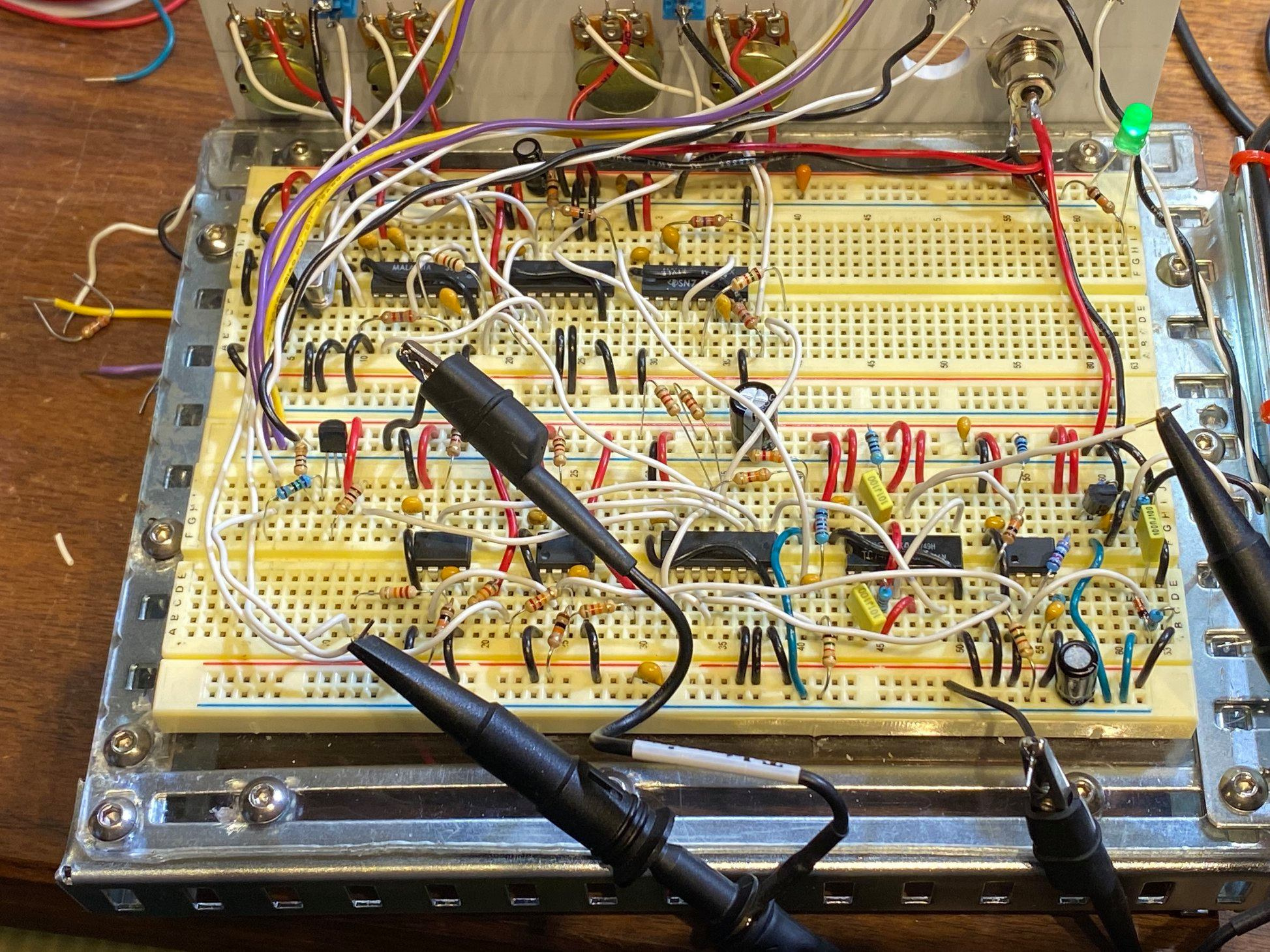
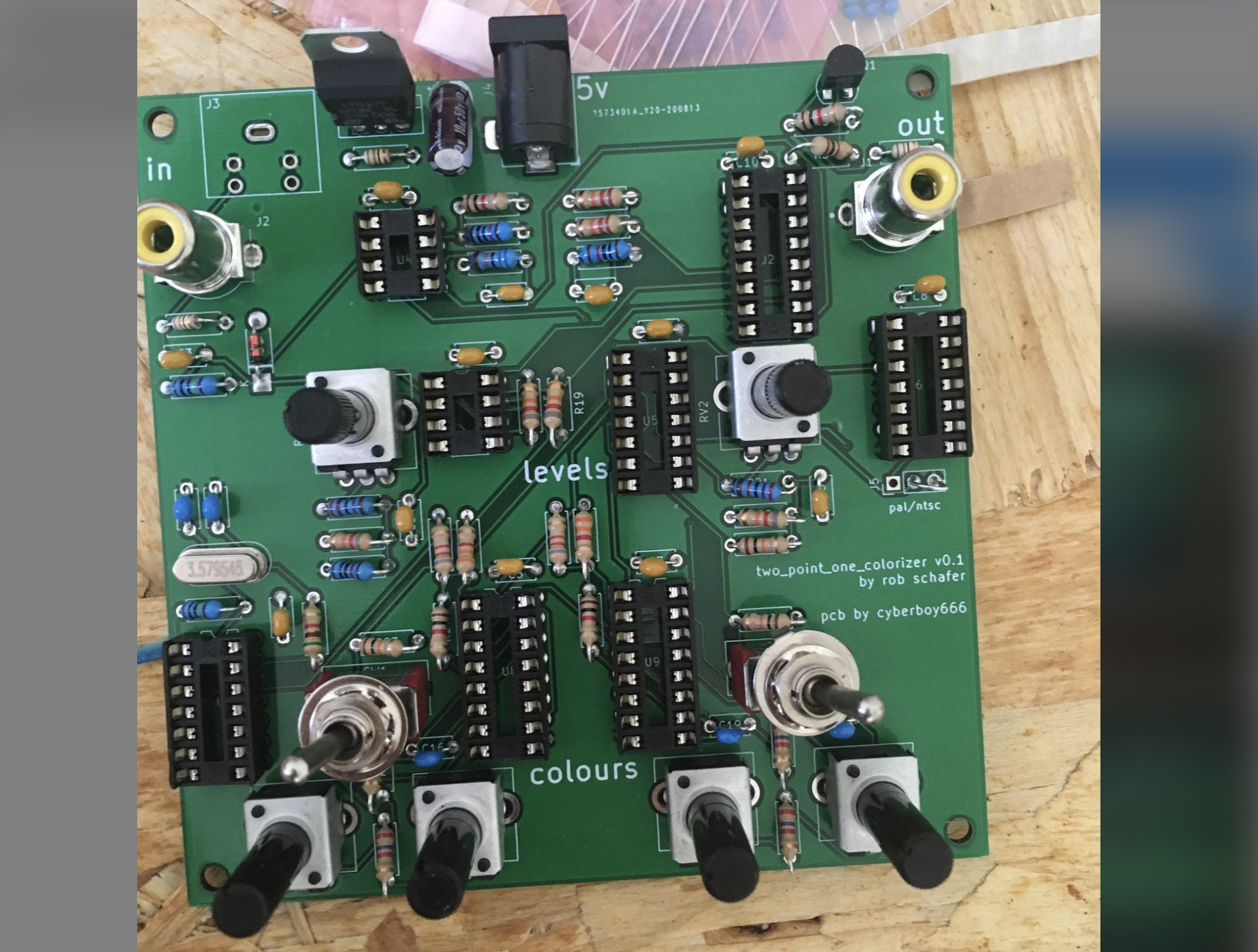
so i started building and testing this adaption of the two_point_one_colorizer circuit this weekend…
it looks nice with all the components on the board !
most parts are working (after finding and fixing some small errors i made)
buuuut… having trouble getting anything usable out of the 74221 oneshots for generating the subcarrier …
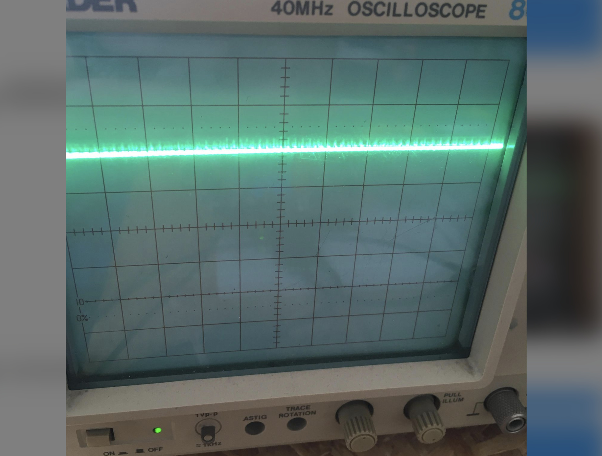
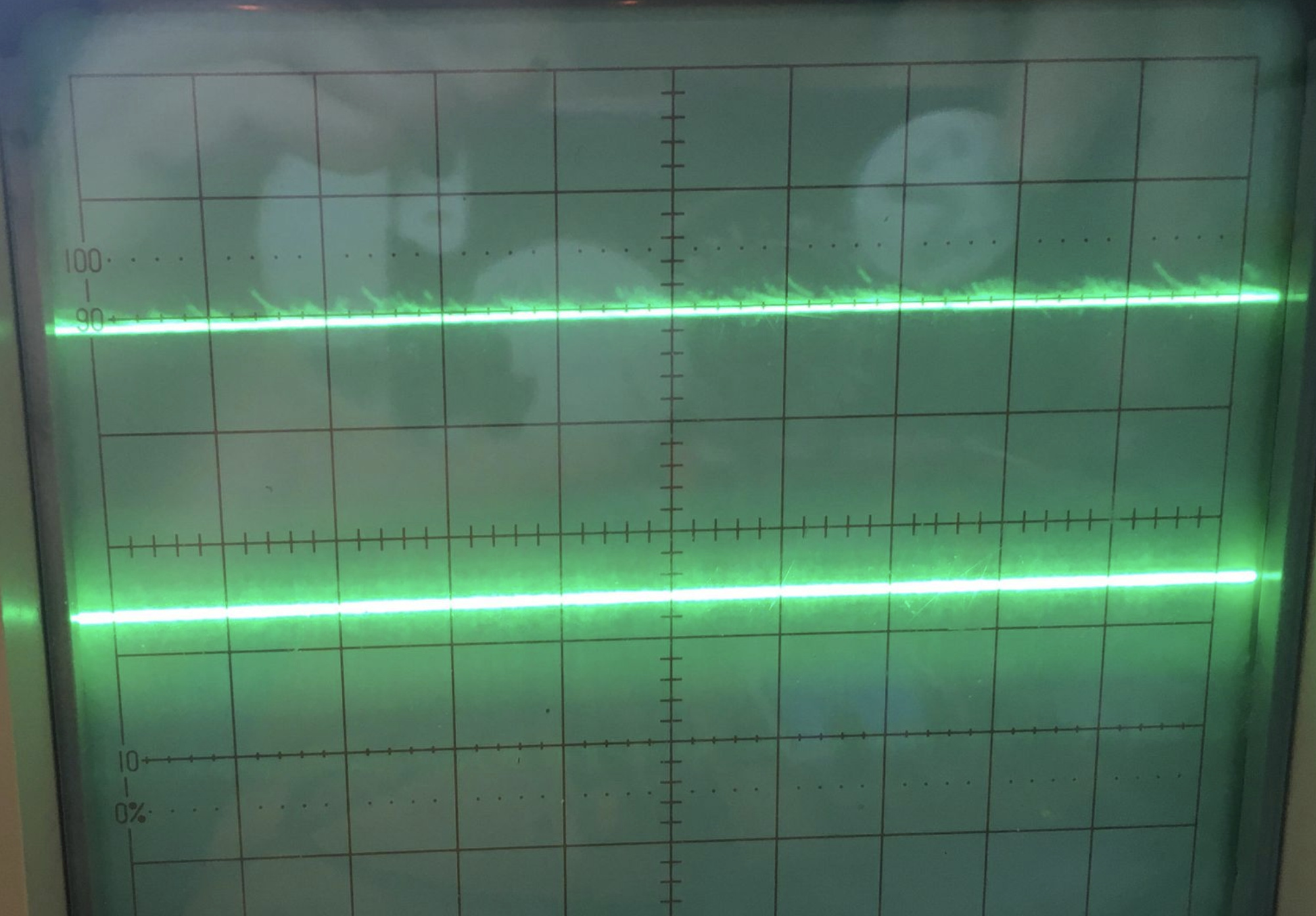
this is the input to the oneshots from the crystal ^^
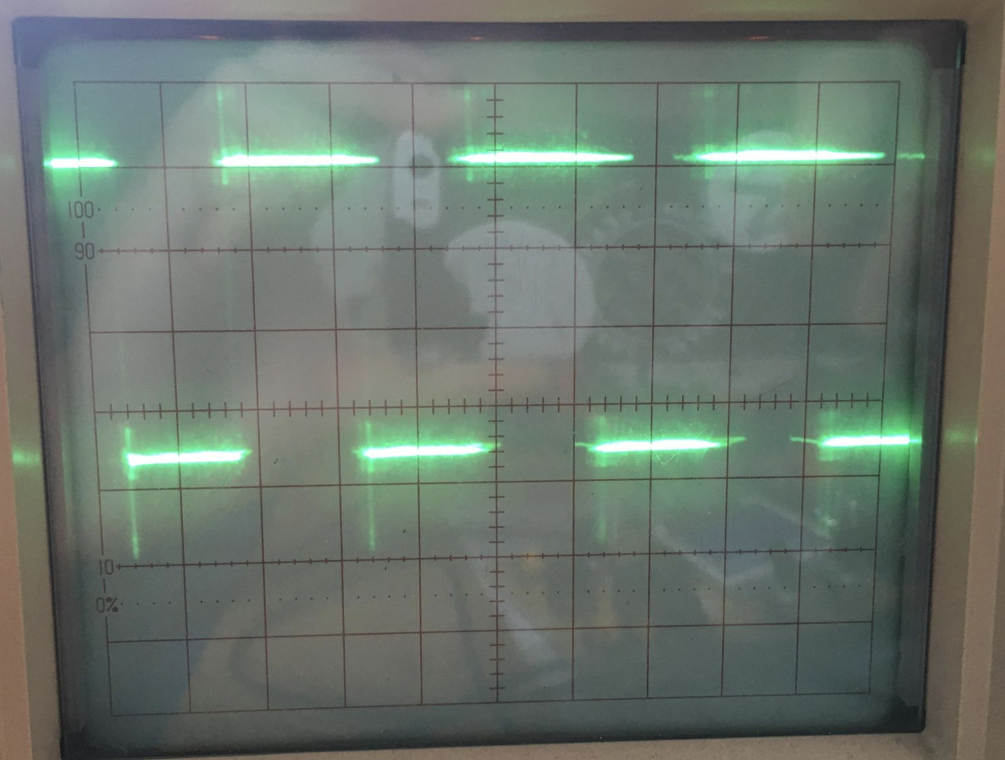
but the output from the first stage is not a pulse (just kindof noise - unless my scope is missing something):
and after increasing the values of Rext/Cext i can get a pulse out from this stage, although it looks like the threshold for something usable is around Cext=100pf , Rext=8k (which doesnt really add up to what im seeing when i do the calculations for Tw )
this is the Qdash output ^^
another very strange thing is that although Qdash is outputing a pulse now , Q pin is still noise → needed to increase Rext even more to get something on this ( ):
):
theories:
- maybe it is working but my scope just cant see it
- the chips im using are these one - SN74221NE4 - maybe they are different to ones that work in this circuit ?
- i tried with some different ics i have ( 74221n 47123n and 74AHCT123AN ) , similar. results - actually the 74AHCT123AN seemed the most stable at lower pulse widths / for the Q vs Qdash problem .. but still none give the desired result in the circuit
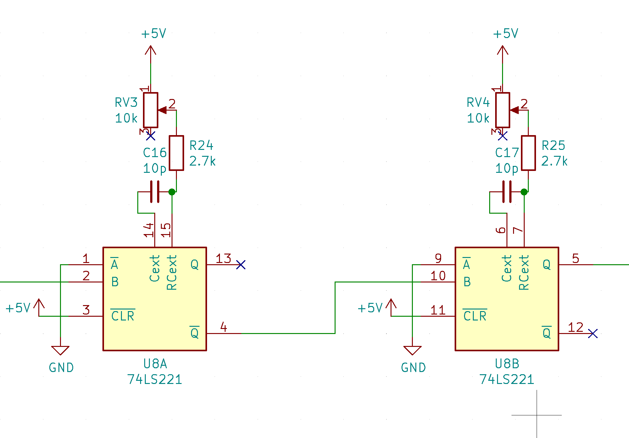
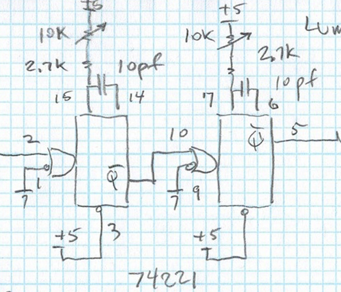
- theres a slight ambiguity on this part of the handdrawn schematic - it says Qdash for the output pin5 but i think this is meant to be Q ? looking at @schaferob’s breadboard i can see the output is indeed pin5
- comparing @schaferob’s breadboard to the schematic i can see that the CLR pins are high in the drawing but not connecte on the breadboard ? i tried both ways (giving slightly different results , but neither working how i would expect in the circuit)
any thoughts or ideas on what im doing wrong here ? or something i might have missed ?
1 Like
or another theory -> maybe the 10pf on the schematic is too low ?
(it doesnt really make sense if the formula is Tw = 0.7RxCx ) but i just tried putting 1000pf caps in there instead and now getting something a bit better looking as subcarrier…

update: i think i found my problem -> my crystal is not oscillating at 3.58mHz , i think it is an order of magnitude too slow (still not that good at reading exact values from my scope) , because just compared a scanline to the crystal and can see only 3 or so cycles fit in one scanline rn 
i copied from this in my circuit but i guess something is wrong here
updated update:
with some help from @BastienL finally figured out the problem:
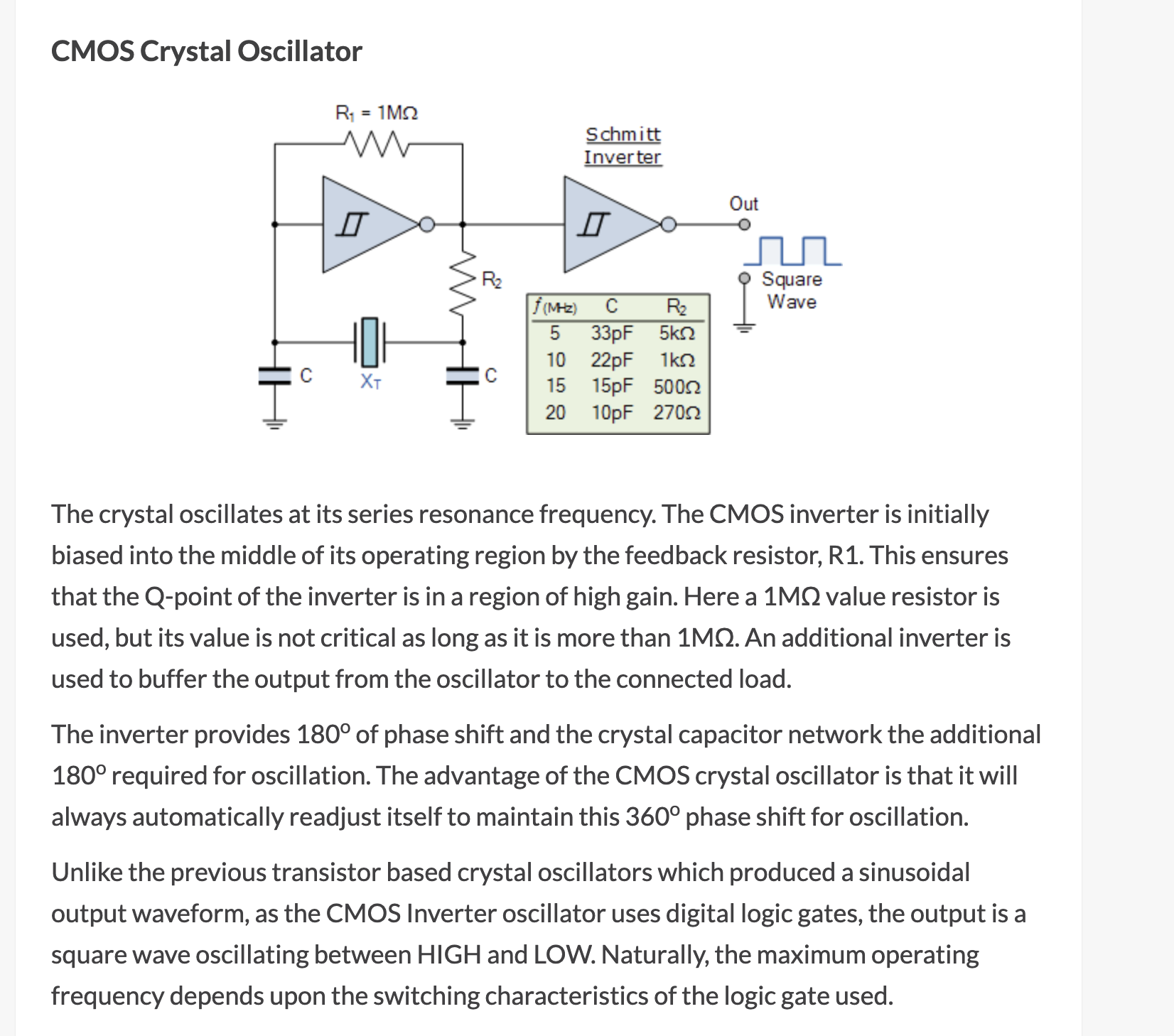
was using a schmitt inverter for the oscillator part of the circuit , which isnt recommended (as discussed here)
it was oscillating but not at the correct frequency , and since i saw a square wave coming out didnt think to check the frequency and then started focusing on debugging the oneshot part of the circuit… not knowing the problem was upstream !
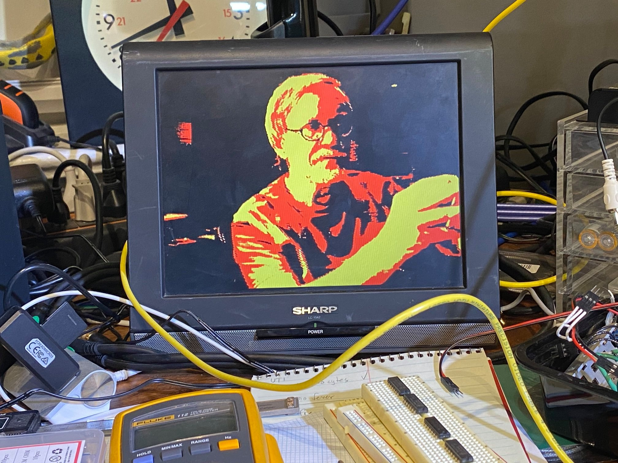
anyway rewired this to the unused xor gate instead and getting good results !
more tests still to come but for now enjoying this lil rainbow !
2 Likes